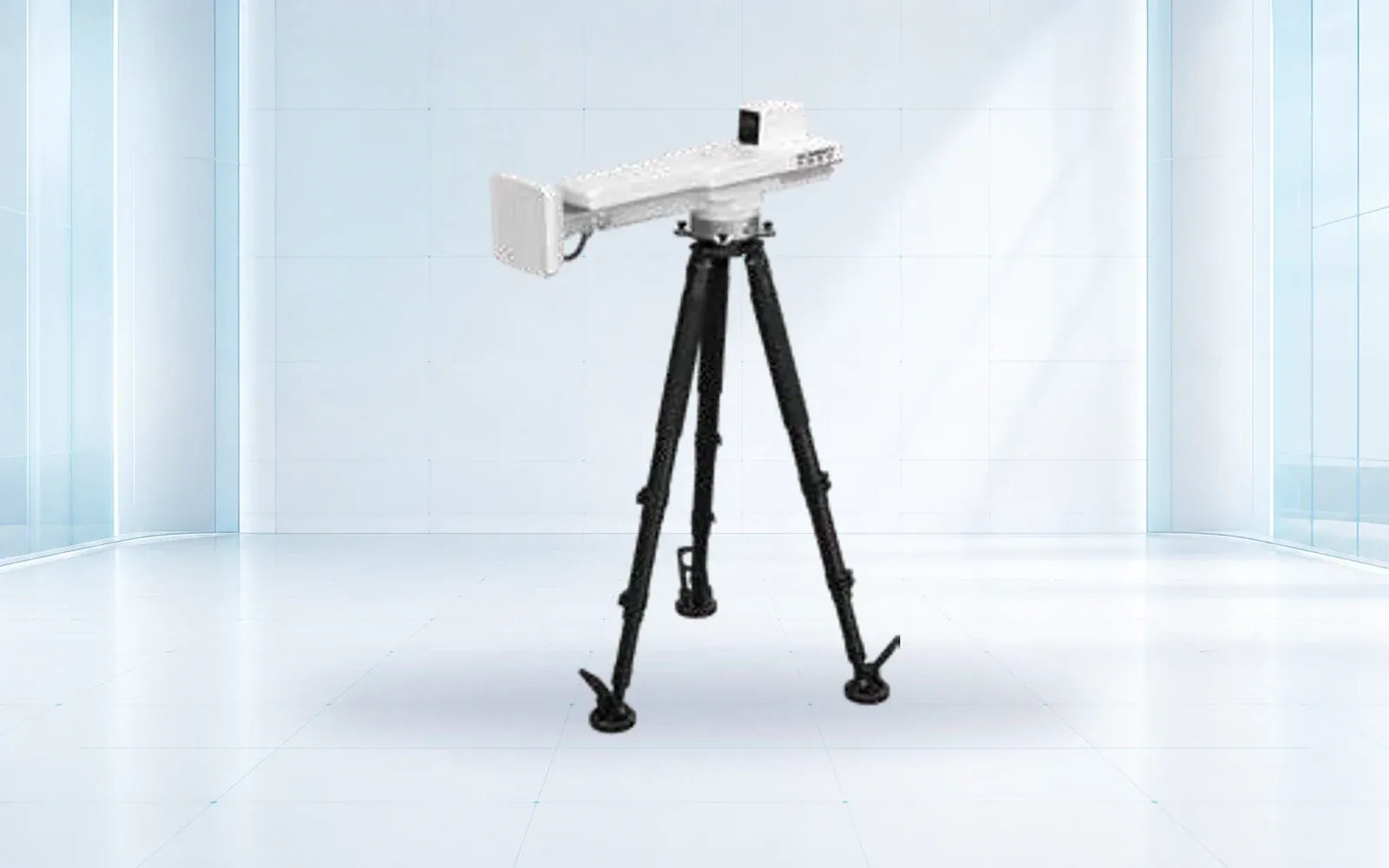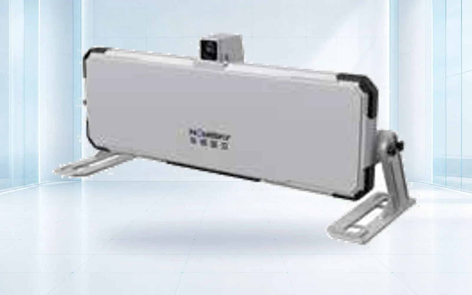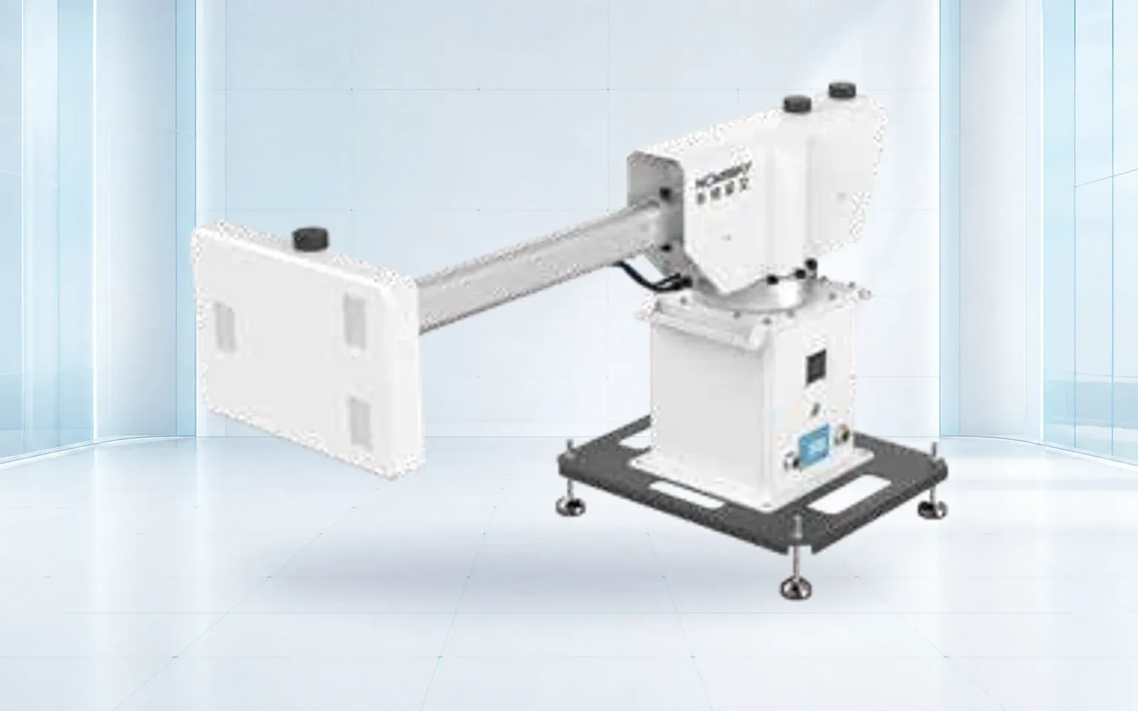
A slope monitoring radar cannot be accepted from maximum range or a precision value alone. The installed system must demonstrate line-of-sight coverage, stable references, repeatable data through changing atmosphere and surfaces, independent corroboration, visible faults and usable outputs under the site's operating conditions.
Table of Contents
- Define the Failure Mode and Required Warning Lead Time
- Understand Line-of-Sight Displacement and Its Blind Directions
- Design Radar Position, Coverage, Reference Areas, and Revisit Time
- Control Atmospheric, Surface, Vegetation, and Equipment Artifacts
- Corroborate Radar With GNSS, Laser Scanning, Survey, and Geology
- Separate Measurement Quality From Alarm and Evacuation Logic
- Run Site Acceptance Across Coverage, Weather, Motion, and Failure Cases
- FAQs
Define the Failure Mode and Required Warning Lead Time
Begin with the geotechnical model: potential failure areas, movement directions, expected rates, benches and structures at risk, operational decisions and the time needed to act. Radar is one observation of that model, not a replacement for geological mapping, instrumentation or engineering review.
Specify whether the objective is broad screening, progressive deformation tracking, rapid-change detection, survey support or a trigger input. Identify who reviews the data, who can change an alarm state and how a measured change reaches traffic control, equipment dispatch or evacuation.
The CDC/NIOSH mine slope and subsidence monitoring partnership reflects current industry and research attention to monitoring practice. Site design and acceptance still depend on the local failure mechanism and operating controls.
Understand Line-of-Sight Displacement and Its Blind Directions
Interferometric radar derives change along the path between sensor and reflecting surface. If the true displacement vector points mostly toward or away from the radar, the line-of-sight component is strong. If movement is mostly perpendicular, the reported component can be small even when total movement is significant.
Plot expected movement vectors against candidate radar positions before installation. Consider elevation and side-to-side directions, not only horizontal distance. A second view or independent instrument may be needed where the primary geometry is weak.
The CDC publication on applications of ground-based radar to mine slope monitoring provides useful technical and field context. Use it as background, then validate the selected geometry and processing for the current site.
Design Radar Position, Coverage, Reference Areas, and Revisit Time
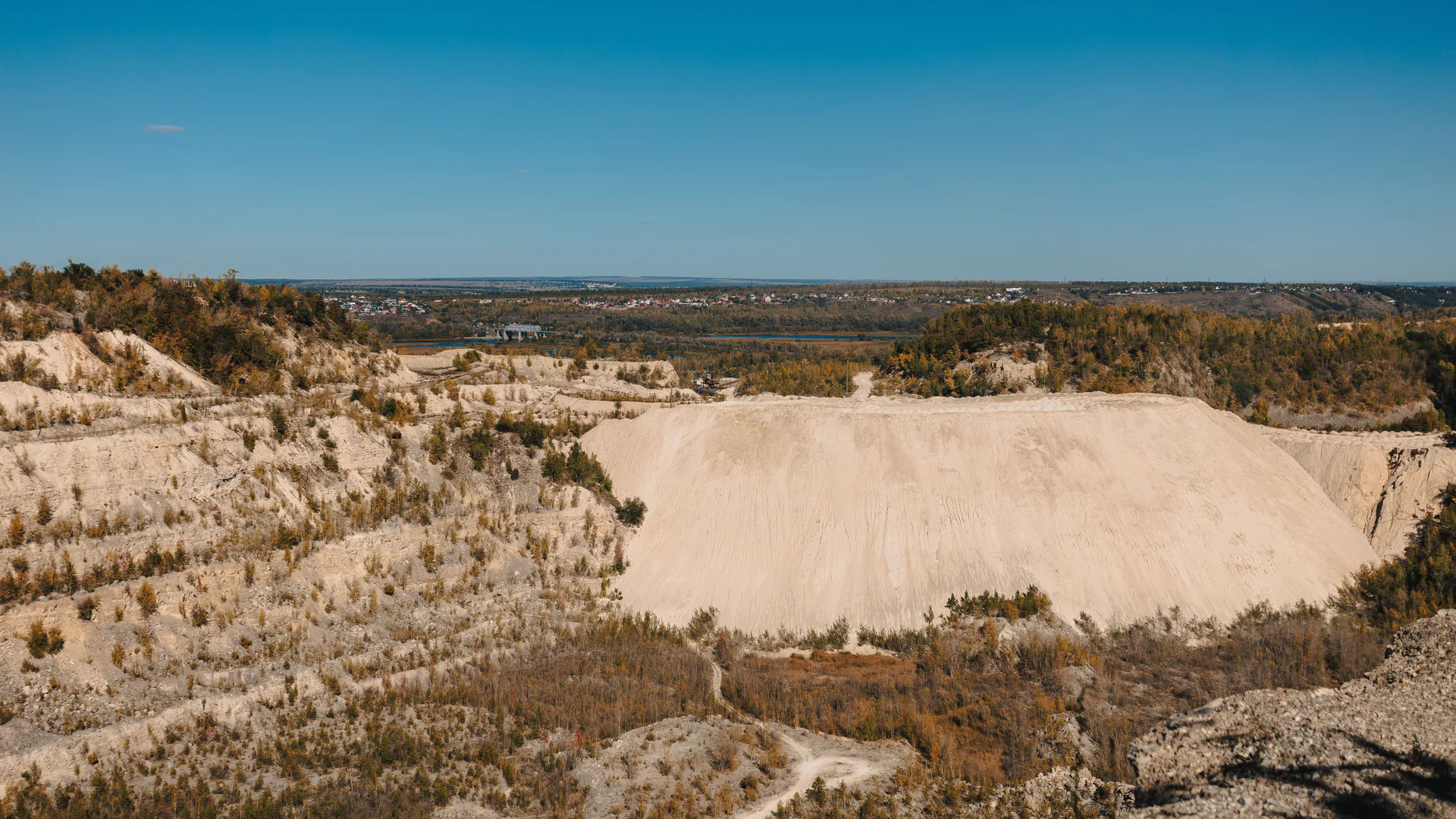
Map line of sight, incidence angle, terrain shadow, active haul roads, blasting, dust, vibration, equipment movement, power and communications. Coverage should be reported as usable coherent cells over the areas of concern, not only a fan drawn from maximum range.
Choose reference areas expected to be stable and visible through operating conditions. Verify their geology and surface behavior; a convenient wall or bench may move, be mined or lose coherence. Monitor reference quality and show the operator when correction becomes unreliable.
Revisit or scan interval must suit the expected movement and required action time. Faster updates can reduce lead-time uncertainty but may trade coverage, noise, network load or processing. Test the complete configured cycle rather than a best-case mode.
Control Atmospheric, Surface, Vegetation, and Equipment Artifacts
Atmospheric changes along the radar path can alter phase. Rain, water films, changing moisture, vegetation, loose material, dust and moving equipment can also change the return. Processing may correct or filter some effects, but acceptance should expose what remains and how it appears to an operator.
Create a site artifact register with weather, blasting, equipment routes, surface work and data-quality effects. Preserve quality layers and correction status next to displacement. A smooth trend with poor coherence or a failed reference should not be presented as high-confidence movement.
Corroborate Radar With GNSS, Laser Scanning, Survey, and Geology
| Method | Observation | Coverage and timing | Corroboration role | Important boundary |
|---|---|---|---|---|
| Ground-based radar | Line-of-sight displacement over coherent areas | Broad area and frequent revisit | Detect and track spatial change | Direction sensitivity, atmosphere and coherence |
| GNSS | Three-dimensional point position | Selected points, continuous or periodic | Independent vector at critical locations | Monument stability and sparse coverage |
| Total station or prism | Line-of-sight point position | Selected prisms and survey cycles | Survey check and structural point tracking | Visibility, reference and weather |
| Laser scanning | Surface geometry and change | Wide area at scheduled epochs | Independent geometry and volume comparison | Registration and lower temporal frequency |
| InSAR | Satellite line-of-sight surface change | Regional coverage and satellite revisit | Historical or regional screening | Coherence, orbit geometry and latency |
| Geological observation | Materials, structures and failure evidence | Field and model dependent | Interpret whether movement is significant | Qualitative and access dependent |
The HAWK-G902 can serve as a GNSS reference and the HAWK-RL1500 as a laser-scanning reference. Define coordinates, time, reference and uncertainty before comparing them with radar; agreement cannot be expected if the instruments observe different components or areas.
The bridge monitoring system guide applies the same measurement discipline to structural response, where traffic, temperature, wind, synchronization and an engineer-owned action model shape the sensor network.
For tailings facilities, the tailings dam instrumentation and response planning guide places surface radar alongside pore pressure, seepage, water management and named decision responsibilities.
Separate Measurement Quality From Alarm and Evacuation Logic
The radar system should output displacement, rate or other derived measures together with timestamp, coverage, coherence or quality, reference state and system health. The geotechnical and operational process determines whether that evidence changes an alarm level or work control.
Do not encode a universal threshold from another mine or slope. Establish thresholds from the failure model, baseline, independent evidence, consequences and required action. Define missing-data and low-quality states so silence is not treated as stability.
The deformation monitoring alarm design guide covers threat modeling, human review and action tables. The mine safety integration guide places slope evidence beside gas, seismic, tailings and personnel systems without collapsing them into one unexplained score.
Before this acceptance work is contracted, the slope monitoring radar cost guide helps buyers fund geometry, site works, power, network, operations, service, relocation, and retest as one lifecycle scope.
Run Site Acceptance Across Coverage, Weather, Motion, and Failure Cases
Build an acceptance cube across area, condition and target state. Include critical slope zones and blind areas; dry, wet, temperature-changing and operational periods; stable surfaces, controlled reflectors or independently observed movement; and power, communications, reference or equipment-position failures.
Measure usable coverage, revisit time, data availability, repeatability, response to independent movement, artifact rate, quality-state accuracy, alarm handoff, logs and recovery. Verify that the system warns the operator when the radar moves, the reference becomes invalid or data stop updating.
Review the results with geotechnical, operations, safety and maintenance teams. Accept the installed configuration and its documented envelope, not a transferable vendor demonstration. Establish revalidation after relocation, material mining progression, major software change or new hazard geometry.
Use the deformation monitoring category to compare reference systems such as HAWK-R5, HAWK-R6 and HAWK-R2S, and the mining safety solution for operational integration. For a site acceptance matrix, contact OMNI UXV with the slope geometry, failure model, required lead time and independent instruments.
FAQs
What does a slope monitoring radar actually measure?
Ground-based interferometric radar measures change in radar phase and derives displacement along the sensor's line of sight for coherent surface areas. It does not directly measure the full three-dimensional movement vector or prove geotechnical stability.
Why can radar miss movement across the slope?
Only the component of movement toward or away from the radar contributes directly to line-of-sight displacement. Movement nearly perpendicular to that direction may appear small, and terrain occlusion or lost coherence can remove coverage.
How should GNSS and laser scanning support radar data?
GNSS can provide independent point displacement, while laser scanning or survey can support broader geometry and change checks at another time scale. They should corroborate defined areas and failure modes rather than be averaged without regard to reference and uncertainty.
What should a slope radar site acceptance test include?
Verify coverage and blind areas, stable references, controlled or independent movement, repeatability, atmospheric and rainfall response, surface and equipment changes, data gaps, communications and power loss, alarm handoff, logs and recovery.