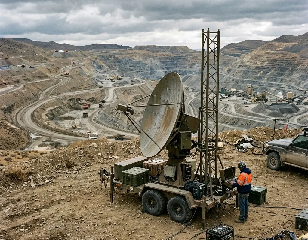
Investing heavily in measurement precision is operationally useless without implementing effective slope monitoring alarm design. Establishing proper deformation monitoring thresholds requires intelligently combining movement magnitude, velocity, and long-term persistence rather than mistakenly relying on isolated, single-point displacement values. Furthermore, a complete and robust slope stability radar workflow must explicitly include clear mining radar alarm escalation procedures. This rigorous approach guarantees that the designated recipient actually receives actionable, contextual data necessary to make pre-agreed safe decisions within critically short time windows, especially when environmental conditions suddenly degrade.
Table of Contents
- 1. Defining the Threat Model
- 1.1. Begin with the movement and consequence model
- 1.2. Thresholds should have context
- 2. Data Integrity and Human Factors
- 2.1. Plan for missing and conflicting data
- 2.2. Commission the human system
- 3. Alarm Design and Testing
- 3.1. Turn the hazard model into an alarm register
- 3.2. Test the complete chain under realistic conditions
- 3.3. Keep alarm performance under change control
- 4. FAQs
1. Defining the Threat Model
1.1. Begin with the movement and consequence model
Describe what may move, how quickly, in which direction and what could be affected. A slow structural drift and an accelerating mine slope require different update rates, coverage and response times. The NIOSH review of ground-based radar for mine slope monitoring describes how radar observations become useful when they are interpreted within the site’s geotechnical and operational context.
For regional or community warning, the landslide early warning system guide extends this site-level alarm logic through hazard knowledge, dissemination, prepared action and end-to-end drills.
The monitoring geometry must provide a stable reference and adequate line of sight. Mount movement, vibration and environmental effects should be separated from the hazard signal where possible. The deformation monitoring systems guide and slope-stability radar overview compare radar roles within that wider measurement plan; the current product catalog provides the relevant OMNI UXV configurations.
| Alarm level | Evidence pattern | Example operational response |
|---|---|---|
| Advisory | Change from baseline with low confidence | Review data quality and local conditions |
| Watch | Persistent movement or corroborated trend | Increase review frequency and notify responsible roles |
| Action | Agreed rate, area and confidence threshold | Pause exposed work and execute the site response plan |
| Degraded | Monitoring, power or reference unavailable | Apply the predefined reduced-confidence procedure |
1.2. Thresholds should have context
A single displacement threshold can be too sensitive during normal variation and too slow during acceleration. Multi-level logic can combine magnitude, velocity, acceleration, persistence, affected area and confidence.
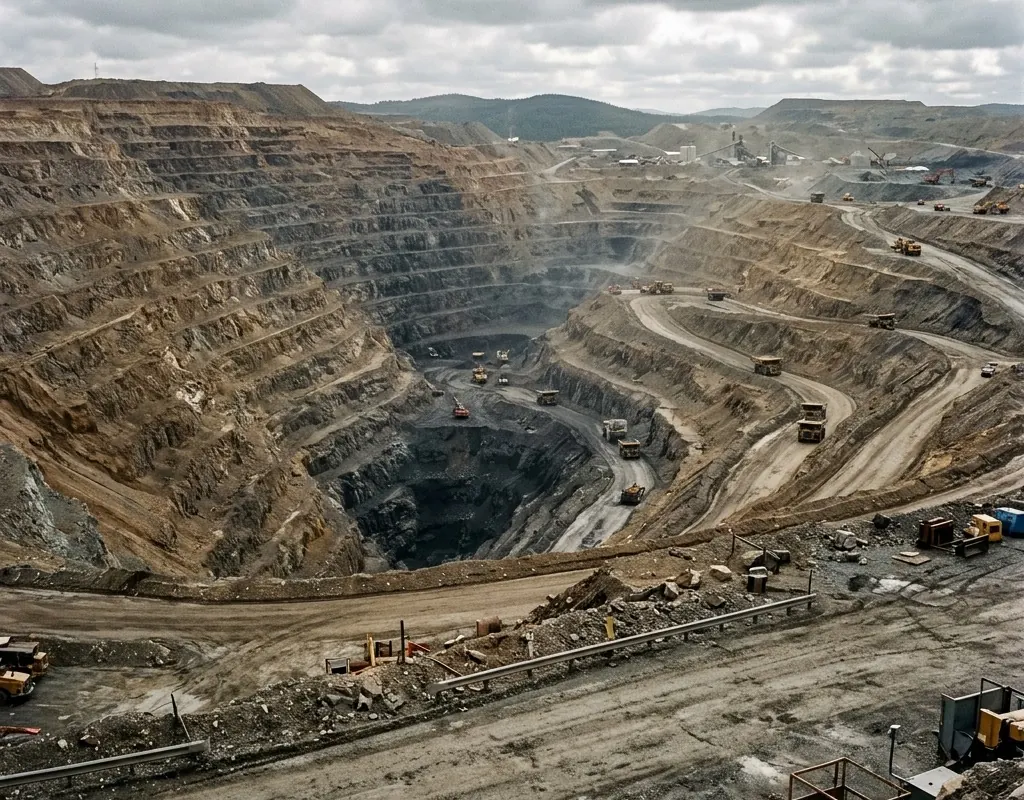
Each level should state who receives it, who verifies it, which operations pause and how the alarm is closed. If the action cannot be stated, the threshold is not finished.
2. Data Integrity and Human Factors
2.1. Plan for missing and conflicting data
Loss of power, communications or a stable reference is itself an operational condition. The site needs a defined response when monitoring is degraded. Independent methods—survey, visual checks, GNSS or another radar view—can be used for confirmation.
The platform should preserve time synchronization, configuration changes, acknowledgements and exported evidence so an event can be reconstructed. The mining safety monitoring architecture shows how area radar, point evidence and aerial inspection can be layered without treating any one signal as infallible.
2.2. Commission the human system
Use simulated movement or controlled alarm injection to test notification, acknowledgement, verification and escalation. Run the test during realistic staffing conditions, not only with the project team watching.
A well-designed alarm is not the loudest one. It is the one that reaches the right person with enough context to make the pre-agreed safe decision. Rapid-deployment scenarios should also be aligned with the disaster response architecture and recorded using the methods in the technical resource hub.
3. Alarm Design and Testing
3.1. Turn the hazard model into an alarm register
The project team should be able to review every alarm in a single controlled register. For each monitored zone, record the measurement source, baseline period, calculation window, threshold logic, confidence rule, notification route, verification owner and required field action. Include a separate entry for data loss, reference instability and communications failure. Those conditions may not indicate ground movement, but they change how much confidence the site can place in the monitoring system.
Do not let the platform’s default labels become the operating procedure. “Red” may mean a high displacement rate in the software, while the site’s emergency plan may use the same color for evacuation. Agree the language and ownership before configuring screens or messages. Where shifts, contractors or external geotechnical reviewers are involved, name a role rather than a person so the workflow survives roster changes.
| Register field | Decision to record | Evidence at commissioning |
|---|---|---|
| Monitored zone | Boundary, reference and assets exposed | Approved map and line-of-sight check |
| Trigger logic | Magnitude, rate, persistence and confidence | Controlled calculation or replay |
| Verification | Responsible role and corroborating method | Acknowledged test notification |
| Action | Pause, exclusion, inspection or escalation | Completed scenario record |
| Recovery | Authority to reset and required review | Signed closure and audit trail |
3.2. Test the complete chain under realistic conditions
Commissioning should include more than a sensor comparison. Establish a stable baseline, introduce a controlled or simulated change, confirm the calculation, verify that the message reaches the intended role and observe whether the response is completed within the agreed time. Repeat the exercise outside normal office hours and with one communications path unavailable. This reveals fragile phone trees, shared accounts and undocumented dependencies that a daytime demonstration will miss.
False-alarm and missed-alarm risk need different tests. A quiet period helps estimate nuisance behavior across weather, blasting, traffic or machinery cycles. A replay or controlled target helps verify that meaningful movement is not suppressed by filtering. Results should retain raw data, software settings, timestamps, operator actions and any manual overrides.
3.3. Keep alarm performance under change control
Ground conditions, excavation geometry, vegetation, structures and work patterns change. The alarm design therefore needs a review trigger: after a major site change, sensor relocation, firmware update, new monitored zone, significant event or repeated nuisance alarm. Record why a threshold changed, who approved it and whether historical data remain comparable.
Routine service should also prove that reference points, time synchronization, power backup, storage and notification routes still work. The handover pack is complete when the operating team can explain what an alarm means, what degraded monitoring means, how to verify both and where the evidence is stored—not when the installation merely shows live measurements.
4. FAQs
What should trigger a slope-monitoring alarm?
An operational alarm should combine movement magnitude, rate, persistence, affected area, data quality and consequence. One isolated displacement value is rarely enough to justify action.
How should a monitoring baseline be established?
Use a stable, representative period and document reference stability, weather, vibration and site activity. Thresholds should be set only after normal variation and known artifacts are understood.
What must be tested before an alarm workflow is accepted?
Test the complete path from sensing and calculation through notification, acknowledgement, verification and field response, including degraded power or communications and out-of-hours staffing.