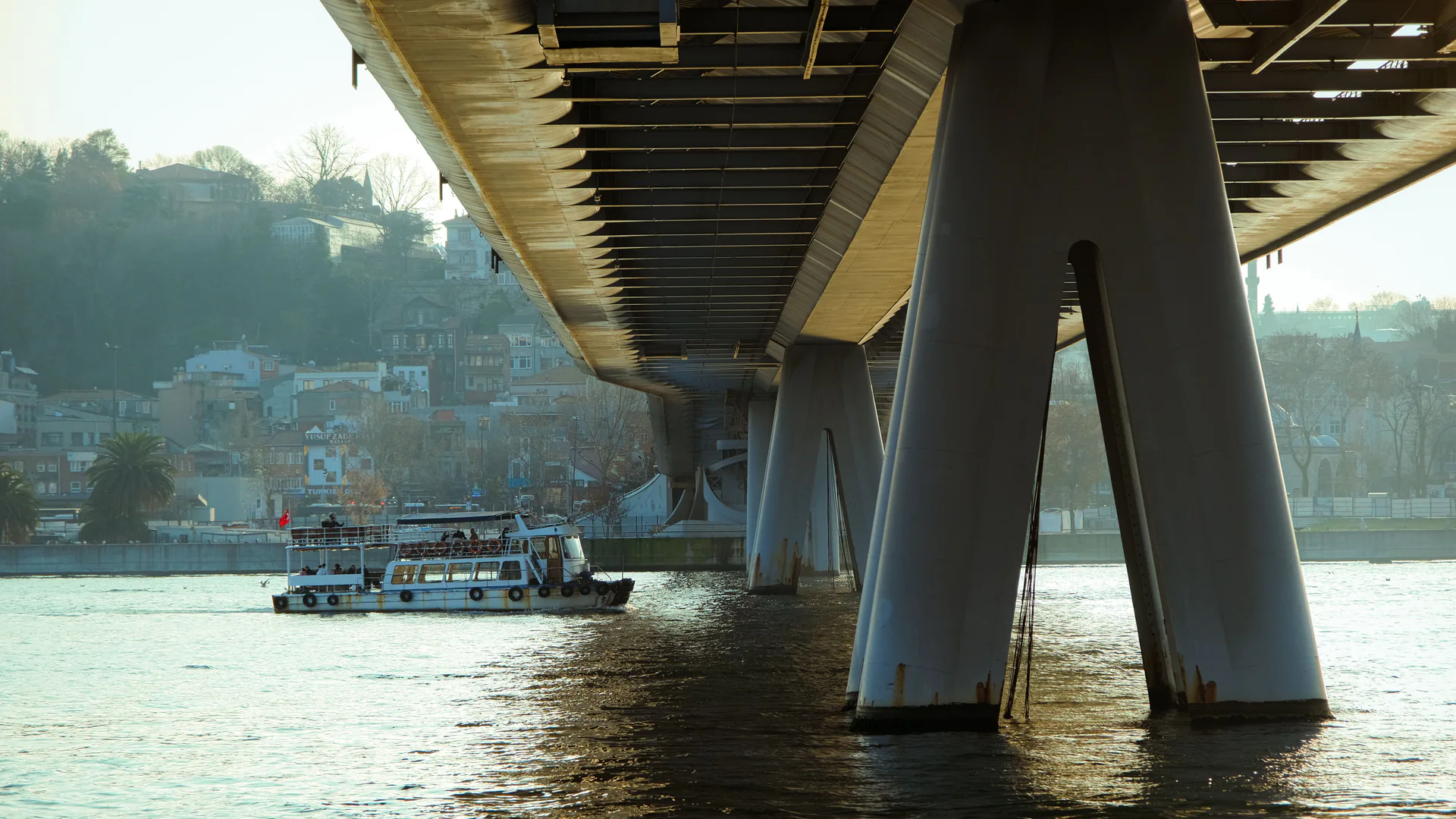
An underwater bridge inspection needs a defensible map of what was observed, by which method, at what quality, and what still requires a diver or another technique. An ROV can extend visual and sonar access, especially in difficult water, but it should be designed as one layer of the bridge inspection program—not presented as a universal replacement for tactile inspection.
Table of Contents
- Start From the Bridge Inspection Program, Not the Robot
- Build an Underwater Element and Coverage Map
- Assign Optical, Sonar, Tactile, and Diver Methods
- Configure the ROV and Imaging Chain for Site Conditions
- Control Current, Tether, Navigation, and Evidence Uncertainty
- Hand Off Unresolved Conditions to Divers and Engineers
- Accept the System With Known Targets and Blind Zones
- FAQs
Start From the Bridge Inspection Program, Not the Robot
Identify the governing bridge inventory, inspection type, interval, qualified personnel, element definitions, prior findings, scour information, plans, and owner procedures before selecting an ROV. The inspection program determines what must be observed and who can accept the result. Vehicle access alone does not change those responsibilities.
The Federal Highway Administration’s current National Bridge Inspection Standards page is the federal entry point for the U.S. bridge inspection framework. Its underwater inspection Q&A makes an important distinction: underwater imaging technology may supplement an inspection; FHWA accepts imaging for Level I inspection, but Level II inspection still requires a diver. Build the method around that boundary rather than a broad “diverless” claim.
Create an underwater element register for every pier, abutment, footing, pile, fender, protection system, and channel or scour area in scope. For each element, state the inspection level, condition or change of interest, required cleaning or tactile work, evidence type, allowable uncertainty, and escalation path.
| Inspection need | ROV optical role | Imaging-sonar role | Diver or other handoff |
|---|---|---|---|
| General Level I condition | Continuous contextual video and defined stills where visible | Geometry and context in low visibility | Required if the accepted inspection level or unresolved condition calls for it |
| Surface detail | Close, controlled views after suitable access or cleaning | May show larger relief, opening, or object geometry | Small-scale, tactile, cleaned, probed, or measured condition |
| Foundation and bed context | Visual record where water permits | Range and shape context around foundation and debris | Scour survey, probing, or engineering method as specified |
| Suspected change | Comparable route and views from prior epoch | Comparable sonar geometry and raw data | Confirmation when resolution or location is inadequate |
The deliverable must distinguish observed clean area, observed candidate condition, indeterminate area, and unobserved area. Without those states, a reviewer cannot tell whether absence of a finding is evidence or simply absence of coverage.
Build an Underwater Element and Coverage Map
Divide each underwater face into a repeatable grid tied to bridge plans, stationing, pile numbers, compass direction, waterline reference, and depth convention. A grid should be usable by both the ROV team and a diver. Avoid relying on vehicle coordinates alone, especially under a bridge where GNSS is unavailable and current or tether force can distort dead reckoning.
Define route geometry for each element. A pier may require waterline-to-bed vertical lanes on every accessible face, perimeter passes around a footing, and separate channel-bed context. Pile groups need a stable pile sequence and a rule for internal rows or occluded faces. Store planned and completed coverage separately.
Use overview-to-detail capture. The overview proves element, face, depth, and surroundings; the detail supports condition review. In turbid water, alternate optical and sonar context can help maintain identity. A close image of concrete or steel without a traceable face and depth may be visually clear but operationally unusable.
Mark blocked areas caused by debris, geometry, current, tether limits, vessel traffic, burial, marine growth, or unsafe access. The reviewer needs a coverage map with blind zones, not an edited highlight reel. Plan how each blind zone will be reattempted, handed to a diver, or accepted as an explicit limitation.
Assign Optical, Sonar, Tactile, and Diver Methods
Optical cameras show color, texture, marine growth, exposed material, and surface geometry when visibility and lighting allow. Their usable range can collapse in suspended sediment or backscatter. Test light placement, intensity, camera angle, and standoff in the actual water; more light can produce more backscatter rather than more evidence.
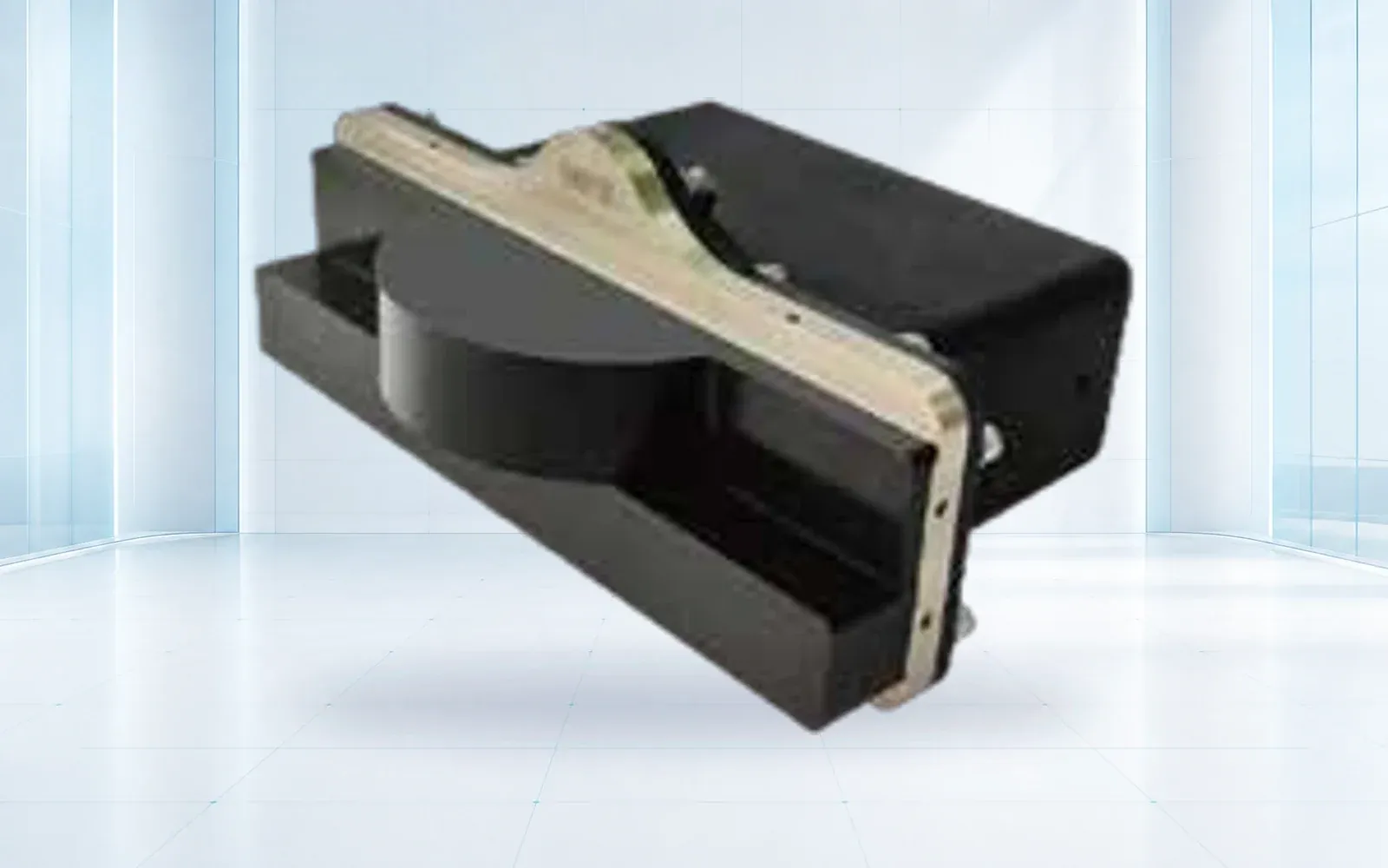
Imaging sonar supports geometry and object detection where optical visibility is poor. The SNR-C400 imaging sonar is a reference for system configuration review. Evaluate frequency or mode, range, angular coverage, update rate, mounting, acoustic shadows, surface orientation, and the smallest target resolvable at the intended range.
Do not interpret a sonar mosaic as a tactile inspection. FHWA’s Q&A cautions that small-scale conditions may not be detected by sonar. Define which indications trigger closer optical work, cleaning, measurement, probing, or a diver. Retain raw sonar data and settings so a qualified reviewer can revisit the evidence rather than receiving only screenshots.
The older but detailed FHWA Underwater Bridge Inspection manual discusses ROV limitations and the role of tactile inspection. Use it as engineering background together with current NBIS requirements and owner procedures. Where a conflict or update exists, the current rule and agency guidance govern.

Configure the ROV and Imaging Chain for Site Conditions
The vehicle must carry the sensors and lighting while preserving control margin in current and turbulence. Assess thrust by direction, vehicle drag, tether diameter and buoyancy, deployment geometry, depth, entanglement risk, recovery method, and usable operating time. A bench endurance figure does not include current, active sonar, lighting, station keeping, and repeated repositioning.
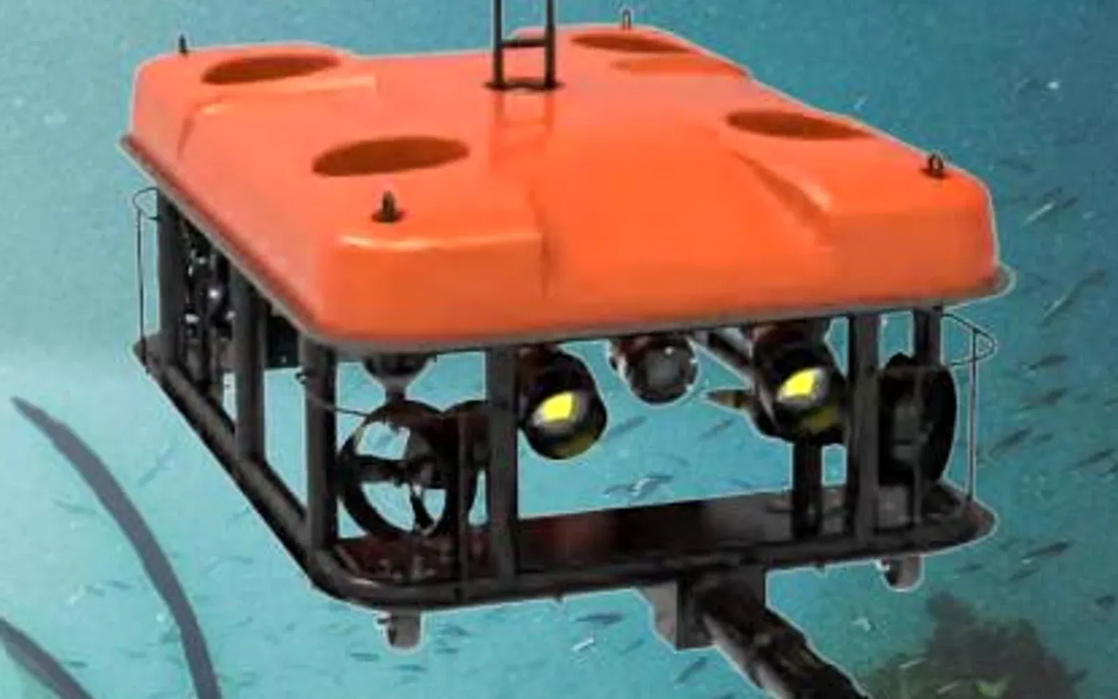
The G70 work-class ROV is a reference platform for configuration discussion. Confirm the actual camera, sonar, navigation, tether, topside power, recording, manipulator or measurement tools, and recovery system required by the site. Product specifications do not establish NBIS compliance or replace qualified inspection personnel.
Build a synchronized evidence chain. Video, stills, sonar, depth, heading, range, navigation estimate, topside annotations, and voice observations should share a time base. If the operator calls out “pier 3 south face, grid B4,” that annotation should be recoverable with the relevant original files.
Design launch and recovery around the bridge and waterway. Consider bank or vessel access, current, debris, propeller hazards, traffic, overhead structure, fall protection, communication between operator and inspection lead, and an entangled-vehicle recovery plan. Do not use the inspection vehicle itself as the only recovery option.
Control Current, Tether, Navigation, and Evidence Uncertainty
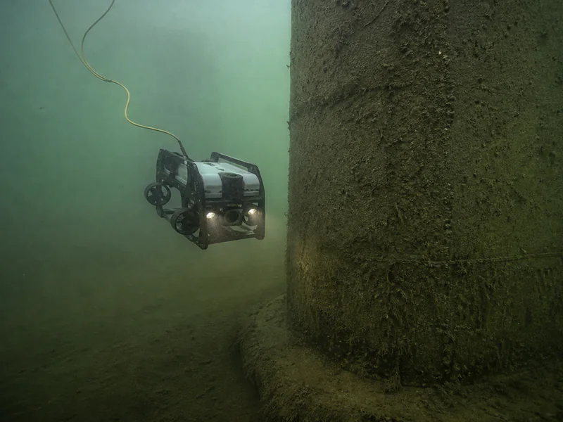
Current and tether force can pull the vehicle away from a nominal route and can make apparent dimensions unreliable. Set operating limits based on control authority and evidence quality, not simply whether the ROV can remain submerged. Record water level, current information where available, visibility, turbidity observations, and changes during the inspection.
Underwater location is an estimate built from element identity, depth, heading, range, tether geometry, acoustic positioning where used, vehicle motion, and visual or sonar landmarks. Declare its uncertainty. A feature location based on “approximately 12 meters down the east face” should not be promoted to survey precision without the required measurement system.
At each route segment, confirm element, face, direction, starting landmark, depth reference, coverage speed, optical or sonar quality, and end landmark. If navigation confidence falls below the accepted level, mark the segment indeterminate and reacquire the reference rather than continuing a potentially misidentified transect.
Preserve originals and non-destructive derivatives. Record camera and sonar settings, any enhancement, measurement method, software version, and calibration. When comparing epochs, distinguish true change from different water levels, orientations, ranges, acoustic settings, lighting, marine growth, or navigation uncertainty.
Hand Off Unresolved Conditions to Divers and Engineers
Use a review funnel: field quality check, coverage reconciliation, candidate grouping, qualified inspection review, assignment of inspection level and evidence limitation, diver or specialty-method request, engineering evaluation, maintenance action, and closure. The ROV operator can support the record without being the person who makes the bridge condition determination.
A handoff package should identify bridge and element, face or pile, grid and depth, original video and sonar intervals, overview frames, candidate observation, uncertainty, access conditions, and the exact question for the diver. “Please inspect pier 2” wastes the location work already done. “Clean and tactile-check the linear feature at pier 2 north face, grid C3, then measure if confirmed” is actionable when the owner’s procedure supports it.
After diver or engineering review, link the conclusion to the ROV candidate. This distinguishes true detections, limitations, and benign features, improving future route design and reviewer training. Retain unresolved cases as such; do not close them as clean merely because another method was delayed.
The drone bridge inspection guide covers above-water aerial evidence. Together, the two workflows can create a more complete bridge record, but their access, uncertainty, inspection levels, and qualified-person requirements remain separate. The critical infrastructure protection solution provides a broader integration context.
Dam faces, intakes, gates, and outlets introduce a distinct hydraulic and appurtenance context; use the dam inspection ROV guide instead of extending bridge procedures by analogy.
Accept the System With Known Targets and Blind Zones
Choose representative piers, pile groups, footings, water depths, current directions, visibility, bottom types, debris, marine growth, and launch conditions. Place safe known targets of different dimensions and orientations where permitted, and include clean areas. Test optical, sonar, synchronized recording, navigation, tether handling, recovery, and evidence handoff.
Score required-area coverage, target resolution by method and range, correct element and grid identity, location repeatability, blind-zone reporting, unusable data, reviewer agreement, false-candidate workload, recovery behavior, and diver handoff quality. The result should name the conditions in which each sensor is accepted.
Exercise loss of optical visibility, sonar obstruction or shadow, time-sync failure, navigation uncertainty, tether restriction, changing current, recorder failure, and aborted deployment. Acceptance is incomplete if the team can demonstrate only ideal collection.
For an asset-specific trial, review the underwater ROV portfolio and technical resources, then contact OMNI UXV with bridge elements, required inspection levels, water conditions, coverage grid, sensor resolution targets, navigation method, and diver-handoff rules.
FAQs
Can an ROV replace divers for underwater bridge inspection?
Not for every task. Current FHWA guidance allows underwater imaging to supplement inspection and accepts imaging for Level I work, while Level II inspection still requires a diver. Tactile, cleaning, probing, measurement, or hands-on confirmation may also require a diver or other method.
How can a bridge be inspected when underwater visibility is poor?
Imaging sonar can provide geometry and target context in turbid water, while optical imaging may work at closer range with controlled lighting. Sonar can miss small-scale conditions, so the plan must define its resolution limit and the trigger for tactile or diver follow-up.
How should ROV observations be located on a bridge substructure?
Use a stable element and face grid tied to bridge plans or a verified model, then retain depth, heading, range, vehicle or camera pose, original media, navigation method, uncertainty, and nearby fixed features.
What belongs in an underwater bridge ROV acceptance test?
Use known targets and representative piers, foundations, current, turbidity, depth, tether routes, and bottom conditions. Score required-area coverage, target resolution, location repeatability, blind zones, navigation uncertainty, recovery, reviewer agreement, and diver handoff.