A dam inspection ROV program is credible when every submerged zone has a defined engineering question, suitable camera or sonar evidence, safe flow and tether controls, reproducible defect location, escalation to another method, and a representative wet acceptance test.
Table of Contents
- 1. Start With the Dam-Safety Decision
- 2. Build a Submerged Asset and Zone Register
- 3. Match Camera, Sonar, Positioning, and Tools
- 4. Control Flow, Intake, Tether, and Recovery Risk
- 5. Preserve Coverage and Defect Provenance
- 6. Define the ROV-to-Diver and Engineering Handoff
- 7. Accept the Workflow on Representative Zones
- 8. FAQs
1. Start With the Dam-Safety Decision
Define which engineering decision each inspection supports: continue operation, shorten the interval, collect a higher-order measurement, clear an obstruction, plan repair, or initiate an urgent response. A continuous video tour is not a decision specification unless reviewers can locate, classify, and revisit every relevant observation.
Identify the owner, regulator, responsible engineer, operating team, ROV team, diver or specialty inspector, and emergency authority. The inspection plan should sit inside the dam-safety program, not replace it. FEMA’s Federal Guidelines for Dam Safety place underwater structures within formal inspection where they affect integrity and call for qualified specialist involvement.
List applicable drawings, prior inspections, known defects, instrumentation trends, repairs, operating events, sediment surveys, and outage constraints. Use them to prioritize coverage while retaining a systematic baseline; chasing only known defects can miss a new condition elsewhere.
2. Build a Submerged Asset and Zone Register
Divide the upstream face, joints, abutment interfaces, foundation exposure, intake towers, trash racks, gates, guides, stoplog slots, valves, conduits, outlets, spillway or stilling-basin elements, instrumentation penetrations, and other appurtenances into stable zones. Use an owner-approved naming convention that survives repeat inspections.
For each zone, record geometry, depth, access, flow, expected visibility, sediment, debris, entanglement, magnetic or acoustic effects, required views, target feature, and alternate method. Reconcile the plan against drawings and field observations; as-built underwater conditions may differ.
| Submerged zone | Primary question | First-line ROV evidence | Possible escalation |
|---|---|---|---|
| Dam face and joints | Surface change, opening, spall or deposit | Controlled video/stills with scale and location | Cleaning, contact measurement or engineering review |
| Intake and trash rack | Obstruction, deformation, fouling or damage | Imaging sonar plus close visual where safe | Debris removal, diver or shutdown inspection |
| Gate/guide/slot | Alignment, visible wear, blockage or coating | Multiple-angle video and geometry context | Contact inspection or maintenance access |
| Toe/foundation interface | Scour, sediment, exposure or displaced material | Sonar coverage and targeted visual | Bathymetry, probing or geotechnical review |
| Conduit/outlet | Debris, surface condition and access limitation | Tethered transit with distance/heading record | Specialty crawler, diver or dewatered inspection |
FEMA’s Model State Dam Safety Program lists underwater faces, trash racks, inlets, and other submerged elements among specialized inspections. The owner and regulator determine scope and interval; the register makes that scope inspectable.
3. Match Camera, Sonar, Positioning, and Tools
Visible cameras need clean optics, controlled lighting, short enough standoff, stable motion, appropriate angle, scale, and original recording quality. In turbidity, lighting can increase backscatter; move closer under a safe procedure rather than only adding power.
Imaging sonar supports navigation, structure recognition, standoff, obstruction search, and target reacquisition when visibility collapses. Specify range, field of view, resolution, update rate, mounting, acoustic shadow, display, recording, and interpretation. Sonar evidence should retain settings and geometry, not just a screenshot.
Positioning may combine surface GNSS, tether layback, depth, heading, altimeter, Doppler velocity, acoustic systems, known structural features, or visual markers. Define location uncertainty by zone and decision. Vehicle position does not automatically locate an obliquely viewed defect on the structure.
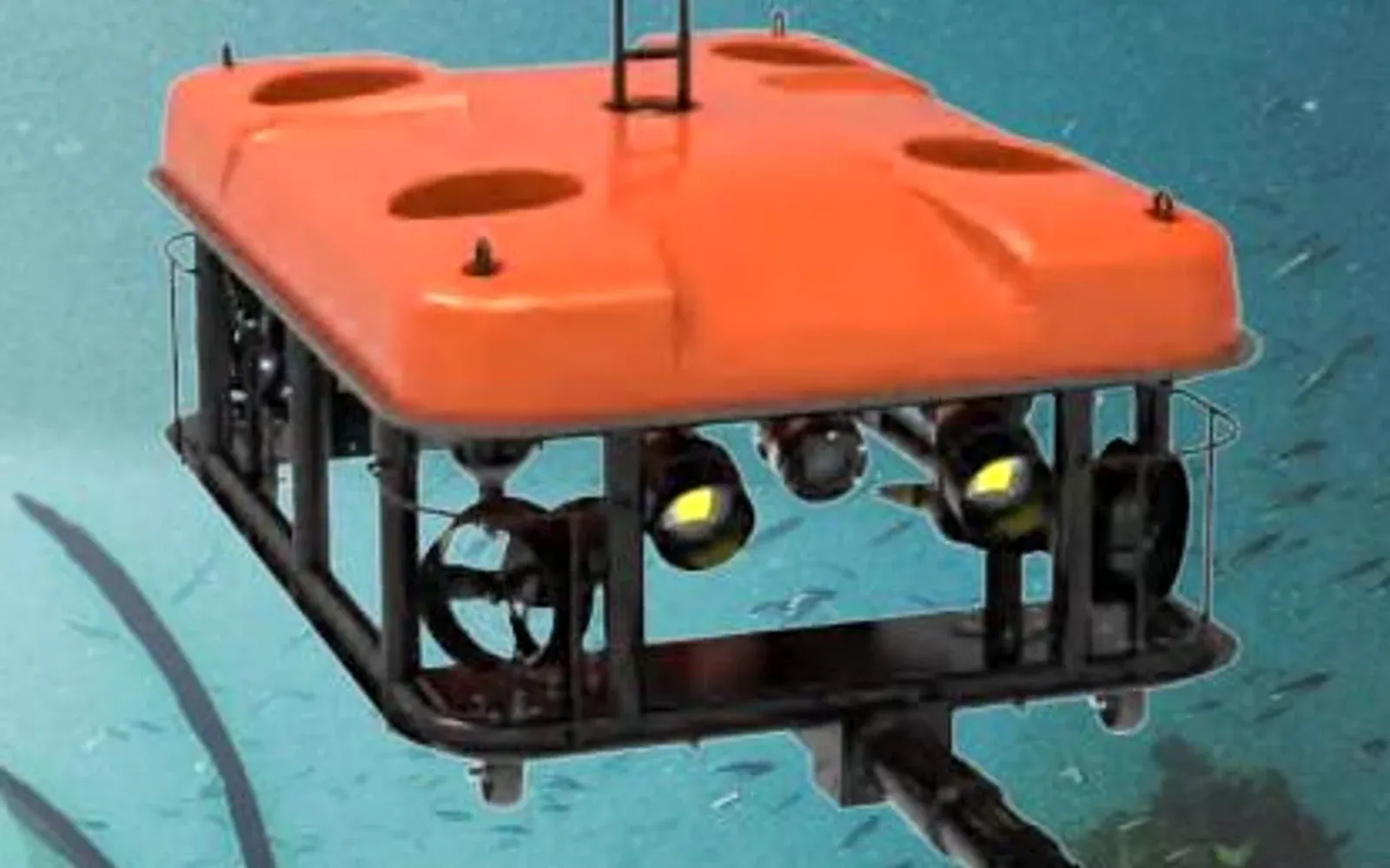
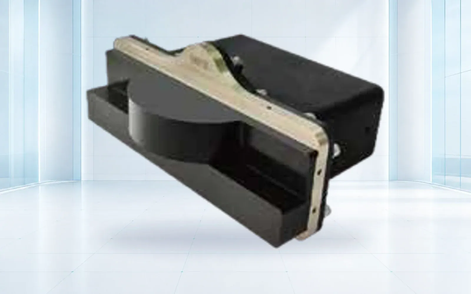
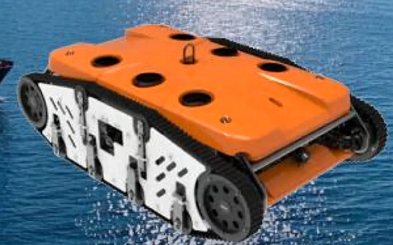
The G70 ROV and SNR-C400 imaging sonar can be evaluated as vehicle and sensing elements. The Q180 cleaning ROV is relevant where an approved cleaning task is part of access; cleaning and inspection acceptance should remain distinct.
4. Control Flow, Intake, Tether, and Recovery Risk
Obtain the actual hydraulic and operating state before deployment. Define gates, pumps, turbines, outlets, spill, leakage, level changes, and control-room actions that can create flow or entrapment. Establish isolation or safe limits where required, lockout and communication responsibilities, and an immediate abort authority.
Plan the tether route from launch point to every zone. Avoid sharp edges, rack openings, cables, debris, moving components, and paths where current can pin the tether or vehicle. Use suitable fairleads, protection, pay-out control, markings, load awareness, and a tether operator who understands the structure.
Predetermine recovery for lost visibility, failed thruster, snag, lost command, damaged tether, power loss, high current, weather, or unexpected gate movement. Do not rely on pulling the tether unless the vehicle and tether are designed and the situation is approved for that recovery load.
5. Preserve Coverage and Defect Provenance
Run a field quality gate zone by zone: correct asset ID, planned view complete, target detail usable, sonar and video synchronized where needed, navigation and settings present, originals intact, and exceptions logged. Mark unobserved areas explicitly with reason and recommended next step.
Each finding should include dam, structure, zone, depth/elevation reference, side or face, view direction, original media IDs, sonar settings where relevant, vehicle position and uncertainty, environmental and operating state, dimensions or scale method, reviewer, and disposition. Store annotations as derivatives linked to immutable originals.
Repeat inspections need comparable viewpoints and location conventions. If surfaces are cleaned between epochs, record method and extent. Apparent change can come from lighting, turbidity, sonar range, angle, sediment, or processing; preserve enough context to separate those effects.
6. Define the ROV-to-Diver and Engineering Handoff
An ROV can screen broad areas, reduce exposure, inspect before a dive, monitor a diver, or return to known points. It may not provide tactile assessment, reliable thickness, samples, torque, close contact measurements, or access behind obstructions. State the threshold for another method before collection begins.
Use finding classes such as no indication, observation, indeterminate, monitor, confirm by another method, maintenance, and urgent engineering review. Do not infer structural severity from image appearance alone. The responsible engineer should approve defect taxonomy and escalation.
The U.S. Bureau of Reclamation describes ROV photogrammetry, HD video, and laser scanning for a Trinity Dam intake-tunnel research project. It shows the value of combining remote methods, but project evidence must still be judged against the owner’s approved inspection purpose.
For a related civil-asset workflow, see the underwater bridge inspection guide. Its foundation and pier lessons help with location and handoff, while dam hydraulics and appurtenances require their own procedure.
7. Accept the Workflow on Representative Zones
Select areas that represent wall geometry, joints, racks, intakes, outlets, sediment, low visibility, depth, flow within the approved envelope, launch constraints, acoustic shadows, and clean surfaces. Include known targets and blank areas, plus safe simulations of lost visibility, degraded propulsion, and tether restriction.
Score required-zone coverage, target resolvability, sonar detection, location repeatability, missed and unusable areas, false candidates, tether handling, setup and recovery, operator workload, evidence completeness, reviewer agreement, and handoff to the dam record. Report by zone and condition.
Approve an operating envelope and retest triggers for changes in ROV, camera, sonar, tether, positioning, software, launch point, hydraulic condition, or defect taxonomy.
Review the underwater systems portfolio, critical infrastructure solution, and technical resources, then contact OMNI UXV with the zone register, hydraulic controls, evidence questions, positioning method, and wet-test targets.
8. FAQs
Can an ROV replace divers for every dam inspection?
No. An ROV can reduce exposure and collect repeatable remote evidence, but tactile examination, cleaning, sampling, contact NDT, confined access, or repair may still require qualified divers or another approved method.
How can an ROV inspect a dam in turbid water?
Use imaging or forward-looking sonar for navigation and structural context, maintain controlled standoff, retain sonar geometry and vehicle state, and use visual or contact confirmation where the engineering decision requires it.
How often should underwater dam areas be inspected?
Frequency depends on the owner’s dam-safety program, hazard classification, governing requirements, asset condition, operating history, events, and responsible engineer. The ROV does not set the interval.
What proves complete ROV coverage?
A zone register, planned tracks and viewpoints, synchronized media and navigation, explicit missed areas, field quality checks, and a reconciled coverage report provide stronger evidence than video duration alone.