A wind turbine drone inspection is complete only when every required blade zone has usable evidence, every candidate defect can be traced to its location and capture conditions, and the owner knows what review or maintenance action follows. A fast flight and a folder of sharp images do not establish that chain by themselves.
Table of Contents
- 1. Define the Inspection Decision and Blade-Zone Register
- 2. Plan Repeatable Coverage Around Each Turbine
- 3. Match Aircraft and Payload to the Evidence Target
- 4. Control Aviation, Turbine, Weather, and Personnel Risk
- 5. Preserve Image Quality and Defect Provenance
- 6. Move Candidate Defects Into Engineering Review
- 7. Run a Representative Acceptance Trial
- 8. FAQs
1. Define the Inspection Decision and Blade-Zone Register
Start with the decisions the asset owner must make: return the turbine to service, continue operation with a monitoring interval, request another inspection method, plan a repair, or escalate a condition for engineering review. “Collect high-resolution blade images” is not an inspection objective because it does not define the condition, evidence threshold, or owner of the next action.
Divide each blade into a stable location convention. A practical register identifies turbine, blade, spanwise zone, side or surface, leading or trailing edge where relevant, and view direction. The exact naming convention matters less than using the same one in flight planning, review, historical comparison, and the maintenance system. A candidate near “the middle of a blade” is difficult to reproduce; a finding tied to blade B, suction side, outer zone, and a defined edge is inspectable again.
Build a defect-family matrix before choosing aircraft or software. The U.S. Department of Energy’s offshore wind operations and maintenance roadmap discusses blade access, leading-edge erosion, lightning, and inspection or repair challenges. That is a useful reason to distinguish surface change, impact or lightning evidence, coating or edge condition, drainage-area condition, and structural indications rather than putting every candidate into one generic damage class.
| Inspection question | Required aerial evidence | Context to retain | Likely follow-up |
|---|---|---|---|
| Is a surface feature new or growing? | Comparable overview and detail views | Blade zone, side, direction, prior epoch, scale cue | Trend review or closer method |
| Is the leading edge visibly changed? | Controlled views along defined span zones | Standoff, angle, focus, operating state | Engineering classification and repair planning |
| Is there evidence consistent with a strike or discharge path? | Feature view plus surrounding blade context | Original files, both directions where safe, weather history if available | Specialist review; do not diagnose from color alone |
| Was a required area unobserved? | Explicit coverage exception | Reason, attempted view, occlusion or safety limit | Reflight or alternate inspection method |
The register must also say what the drone cannot establish. Visible imagery does not measure subsurface bond condition merely because a surface pattern is present. Thermal data is not a diagnosis without a validated method and suitable environmental conditions. State those boundaries in the inspection specification, not after the first disputed finding.
2. Plan Repeatable Coverage Around Each Turbine
Coverage is a set of accepted views, not a completed orbit. Define the blade state and turbine coordination required for collection. If the rotor must be stopped, indexed, or placed in a particular orientation, assign who controls that state, how it is confirmed, and what prevents an unexpected change while an aircraft is nearby. The flight team should never infer isolation or turbine status from appearance.
For each blade zone, prescribe an overview that proves identity, a primary condition view, and any secondary angle needed to separate a feature from glare, curvature, or occlusion. Maintain a capture order that helps the reviewer follow root-to-tip continuity. If the method uses automated paths, review whether the path preserves target distance and view angle around actual blade deflection and yaw rather than an idealized turbine model.
Record every missing view at the point of collection. Sun glare, low contrast, cloud shadow, precipitation, fog, surface contamination, blade motion, and wind-driven position error can all turn a captured image into an unusable one. The field quality check should answer whether the target detail is visible before the team moves to the next turbine.
Repeatability requires more than waypoint reuse. Store the coordinate convention, blade state, lens, focus method, exposure approach, target distance or scale, and direction of view. When comparing epochs, the reviewer should know whether an apparent change may come from geometry, lighting, compression, or a different sensor.
3. Match Aircraft and Payload to the Evidence Target
Close blade imaging rewards stable low-speed control, predictable braking, controllable camera angle, and sufficient reserve for repositioning. Site overview, access-route documentation, or broader mapping may reward efficient cruise and coverage. Treat those as different mission layers even when one project contains both.
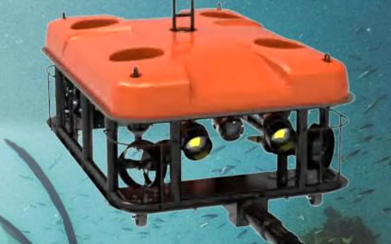
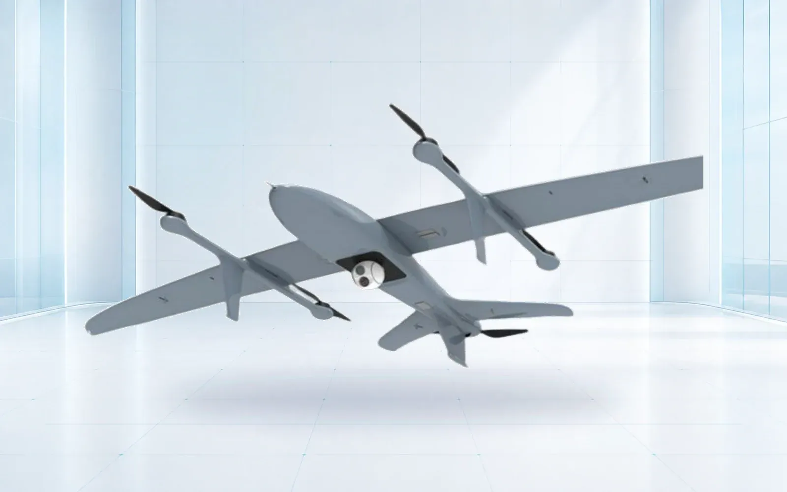
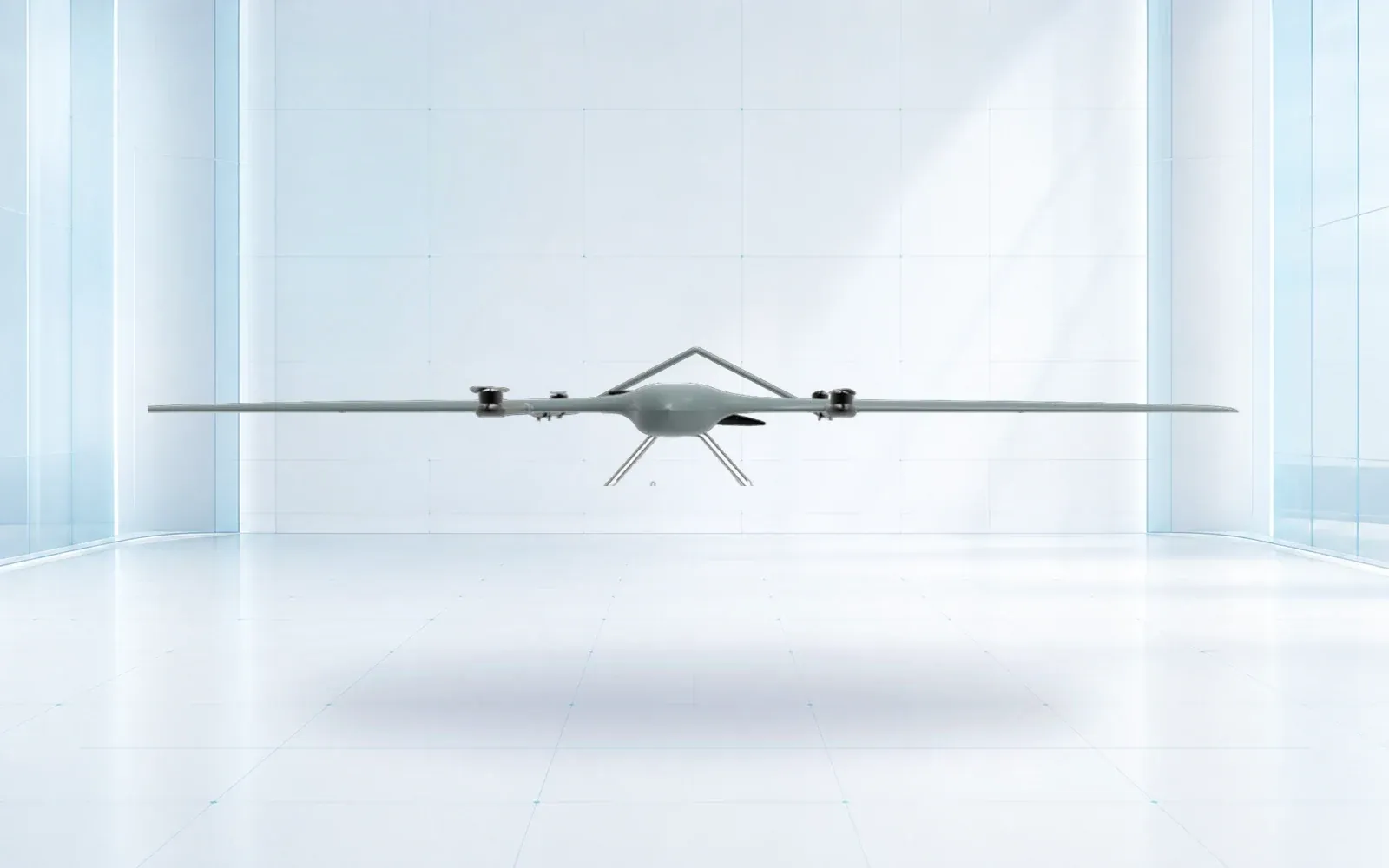
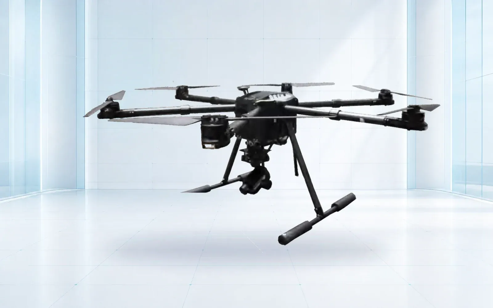
The F4 waterproof multirotor is a reference configuration for close observation when its verified aircraft, payload, link, and environmental limits fit the site. The ZJ-G25 VTOL is a reference for broader-area collection. These links are starting points for configuration review, not a claim that either aircraft satisfies a wind-farm method without an installed-payload trial.
Specify camera performance at the blade, not at the sensor datasheet. The requirement should describe the smallest target feature to resolve, allowable blur, acceptable exposure, view angle, and focus success at the planned distance. Pixel count alone omits lens, distance, motion, atmosphere, compression, and review-display effects.
If thermal imaging is included, define the physical question and validation method. Retain original measurement data when the method requires it, along with settings, ambient conditions, solar history, wind, observation angle, and a matching visible view. A palette can improve presentation, but it must not turn an apparent temperature pattern into an unsupported defect label.
4. Control Aviation, Turbine, Weather, and Personnel Risk
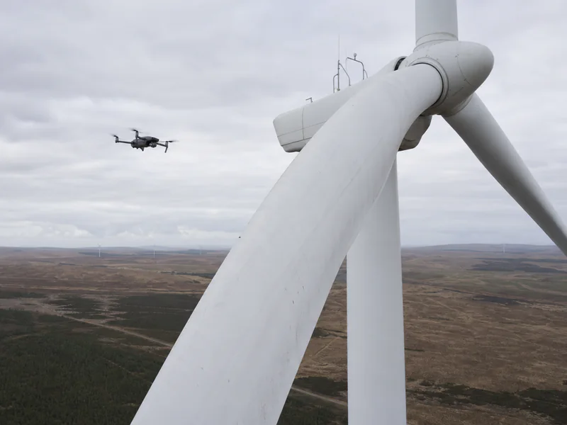
A flight plan near a turbine needs an exclusion model for the blades in every authorized state, tower, nacelle, nearby turbines, cables or cranes, terrain, roads, people, and other site activity. Position uncertainty, wind displacement, command latency, and braking distance must fit within that model. A nominal path that clears a stationary blade is not enough if a gust or navigation degradation can move the aircraft outside the planned envelope.
Predetermine hold, back-away, climb, land, and abort behavior. Review lost-link and return logic with the turbine geometry: a generic straight return or automatic climb can be less safe than a controlled retreat. Observe GNSS, compass, video, and command-link behavior on site with the installed payload rather than relying on an office range estimate.
The Department of Energy’s wind energy safety overview notes hazards including maintenance, lightning, ice, and severe weather. Translate those categories into site-specific stop conditions. A waterproof rating, where applicable, does not make flight in precipitation or icing acceptable, and it does not resolve poor evidence quality.
In the United States, use the FAA’s current Part 107 page as the operational entry point. Airspace, visual-line-of-sight, night, people, remote pilot duties, and any advanced operation must be evaluated for the actual mission. The wind-farm procedure must also coordinate landowner, asset-owner, electrical, control-room, and emergency requirements.
5. Preserve Image Quality and Defect Provenance
Run a field quality gate before accepting a blade. Confirm that every required zone and direction has a usable overview and detail image, the image is sharp at the target, identifiers are correct, originals are intact, and no required area is silently missing. Automation may help flag blur or coverage gaps, but a declared score is not a substitute for checking the evidence needed by the defect register.
Keep original media immutable. Derivatives used for annotation, enhancement, or machine screening should preserve links to the source file and record the software or model version. Do not overwrite the source with a marked-up JPEG. When an automated tool proposes a box or label, store that as a candidate with confidence and review status rather than as an accepted defect.
A finding should carry turbine ID, blade ID, blade zone, surface or edge, view direction, capture time, original media IDs, relevant conditions, reviewer, classification, and disposition. If the location is estimated from aircraft pose or a blade model, record the method and uncertainty. Aircraft coordinates are not automatically the coordinates of an obliquely viewed blade feature.
The NREL discussion of lightning protection for wind turbine blades illustrates why apparently small surface evidence can sit within a larger engineering problem. Use qualified review and the owner’s defect taxonomy; do not infer structural severity solely from visible length, color, or an AI label.
6. Move Candidate Defects Into Engineering Review
Use a controlled funnel: collection quality check, duplicate grouping, candidate classification, qualified review, request for alternate evidence where necessary, maintenance priority, work order, and closure. Separate “not a defect,” “indeterminate,” “monitor,” “inspect by another method,” and “repair” instead of forcing all non-clean images into one severity scale.
Reviewer consistency is part of system performance. Give reviewers the same location convention, required neighboring views, defect definitions, and uncertainty options. Test agreement on a shared set before production and periodically during the program. If agreement falls, investigate the taxonomy, evidence quality, or training rather than simply averaging scores.
The maintenance record should include enough context for a planner to find the same area and understand the evidence. After repair or a higher-order inspection, link the outcome to the original candidate. That closes the learning loop and allows future inspection intervals, field captures, or machine-screening thresholds to improve from confirmed outcomes.
For a comparable asset-to-work-order pattern, see the drone power line inspection guide. Its conductor and insulator evidence rules are not transferable to blades, but its insistence on stable asset identity and repair closure is relevant. The critical infrastructure protection solution shows how aerial evidence can sit beside other site sensing and response systems.
7. Run a Representative Acceptance Trial
Do not accept the workflow on one clean turbine in favorable light. Select the turbine models, hub heights, blade finishes, orientations, backgrounds, wind regimes, sun angles, and communications conditions that represent the intended program. Include known visible targets, deliberately clean zones, difficult leading or trailing-edge views, and safe simulations of rejected captures or link degradation.
Score required-view coverage, target resolvability, correct blade-zone identity, location repeatability, unusable capture rate, reviewer agreement, false-candidate workload, time to qualified decision, and successful maintenance handoff. Report results by condition rather than hiding weak cases inside a fleet average.
Exercise abort, reflight, missing-view, uncertain-finding, and alternate-method handoffs. Acceptance should state the operating envelope and retest triggers: a new aircraft, lens, payload, flight-control version, automated review model, turbine family, or material change in capture geometry.
To prepare a site trial, review the industrial UAV portfolio and technical resources, then contact OMNI UXV with the turbine families, blade-zone register, evidence target, operating constraints, and acceptance measures.
8. FAQs
Can a drone replace every wind turbine blade inspection method?
No. A drone can provide repeatable external visual or thermal evidence where the approved method supports it, but internal, tactile, acoustic, rope-access, ground-based, or other nondestructive tests may still be required for particular defect families.
How should blade coverage be measured during a drone inspection?
Measure delivery of the required views for every defined blade zone at the accepted image quality. Flight completion, image count, and turbine count are useful production measures, but they do not prove defect-relevant coverage.
Which records should accompany a possible blade defect?
Retain turbine and blade identity, blade zone, side, view direction, original media, capture time, camera settings, relevant weather and operating state, reviewer decision, and any follow-up inspection or work order.
What belongs in a wind turbine drone acceptance trial?
Use representative turbine geometries and surface conditions, include known targets and clean areas, and score coverage, resolvable detail, location accuracy, repeatability, reviewer agreement, nuisance candidates, contingencies, and maintenance handoff.