An underwater pipeline inspection is defensible only when the operator can show which side of which segment was observed, how well it was positioned, what the sensors could resolve, and how each anomaly reached a qualified integrity decision. ROV video without that context is footage, not a condition record.
Table of Contents
- 1. Define the Segment and Integrity Question
- 2. Build a Coverage and Positioning Design
- 3. Choose Visual, Sonar, and Contact Methods by Condition
- 4. Control Stand-Off, Speed, Lighting, and Marine Growth
- 5. Record Anomalies and Surrounding Seabed Consistently
- 6. Escalate to Qualified Integrity Assessment
- 7. Accept the System on a Representative Route
- 8. FAQs
1. Define the Segment and Integrity Question
Start with a route register that the pipeline owner recognizes: system and line ID, start and end references, chainage convention, diameter, coating, burial state, crossings, tie-ins and previous anomalies. Split the route where inspection method or risk changes. A long “survey line” that passes several asset types is difficult to reconcile with integrity records.
List the questions the mission must answer. These may include whether a segment remains exposed or buried, whether a free span has changed, whether external protection appears damaged, whether debris or an anchor interaction is present, or where a contact measurement should be made. Keep visual observation separate from conclusions about wall condition or fitness for service.
The integrity team should approve the anomaly taxonomy and escalation rules before launch. The ROV crew observes and records; qualified personnel decide what the evidence means for maintenance, further inspection or engineering assessment.
2. Build a Coverage and Positioning Design
Define coverage by observable surface and route progress, not vehicle distance. A common plan may include passes along both sides and over the crown, additional views at supports, crossings, connections and free spans, and a documented method for the lower quadrant where geometry permits. Record sections hidden by burial, marine growth, debris, structures or safe-operating limits.
Positioning needs a stated reference and uncertainty. Surface-vessel GNSS alone locates the vessel, not the ROV. An acoustic system may estimate subsea position, while vehicle heading, depth, altitude, odometry and observed pipeline chainage help maintain local context. Latency, sound-speed conditions, geometry and sensor drift can all affect the final location.
Use event markers at known features and reconcile route progress after the dive. If the uncertainty is larger than the spacing between similar features, rely on chainage and asset-feature sequences rather than a coordinate with false precision. Store raw navigation and event data so later reviewers can reconstruct the method.
3. Choose Visual, Sonar, and Contact Methods by Condition
Sensor selection begins with water and the integrity question. Visible cameras need workable clarity, lighting and stand-off. Imaging sonar can find and follow structure when optical range collapses. Contact tools can obtain a specific measurement only when the vehicle can reach, stabilize and prepare the target as the method requires.
| Question | Primary method | Required context | What it does not prove alone |
|---|---|---|---|
| Is the pipe exposed and continuous? | Video plus imaging sonar in poor visibility | Route position, range, scale and view direction | Remaining wall thickness |
| Has a free span or support condition changed? | Profile views, sonar geometry or survey method | Seabed reference, chainage and uncertainty | Structural acceptability without analysis |
| Is coating or external protection visibly damaged? | Close visual record after adequate cleaning | Lighting, surface condition and multiple views | Depth of metal loss beneath the surface |
| Is a local NDT measurement needed? | Method-specific contact tool | Calibration, surface preparation, contact quality and location | Condition outside the tested points |
| Has surrounding seabed changed? | Sonar or bathymetric survey | Repeatable reference and comparable acquisition | Direct pipe material condition |
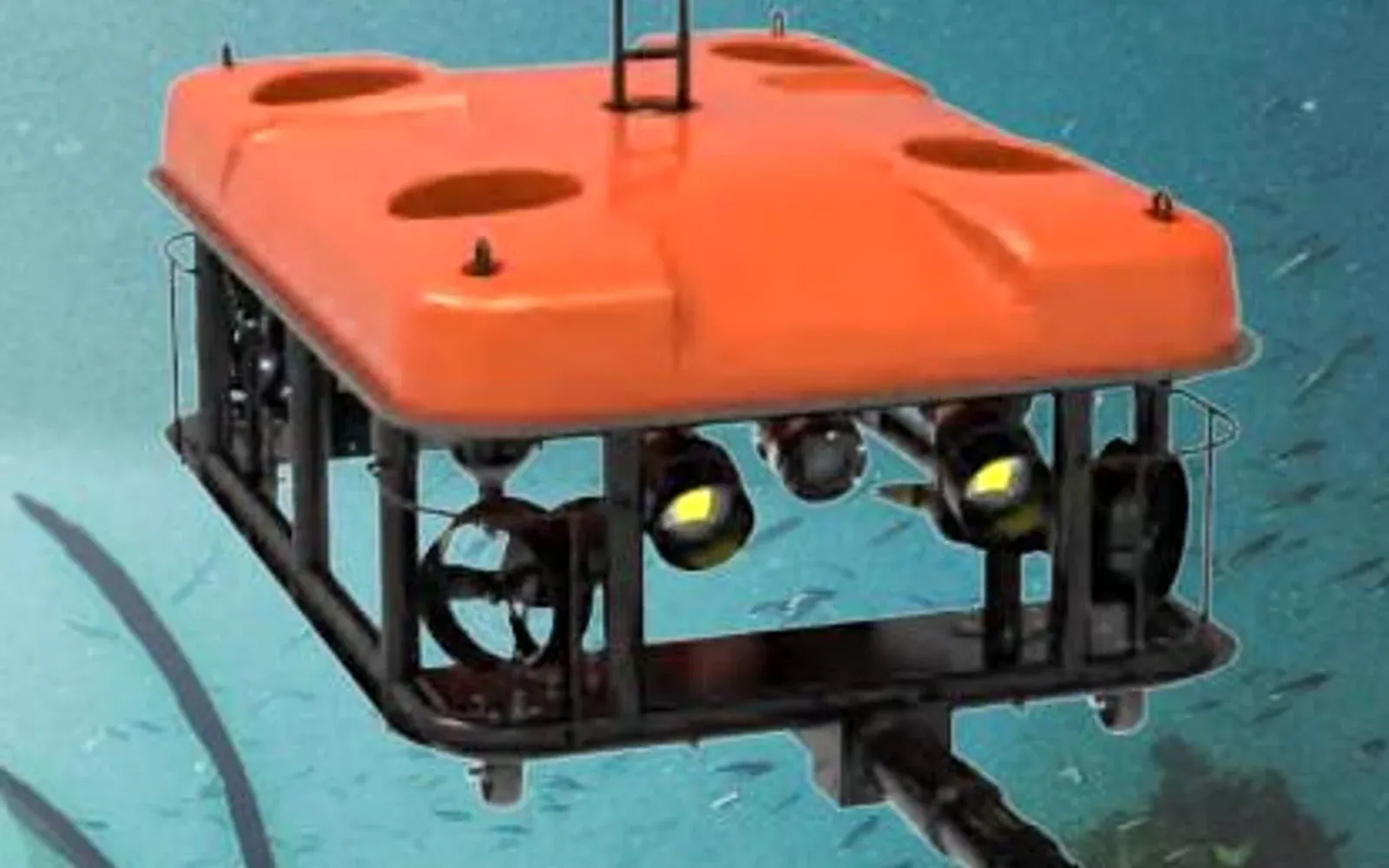
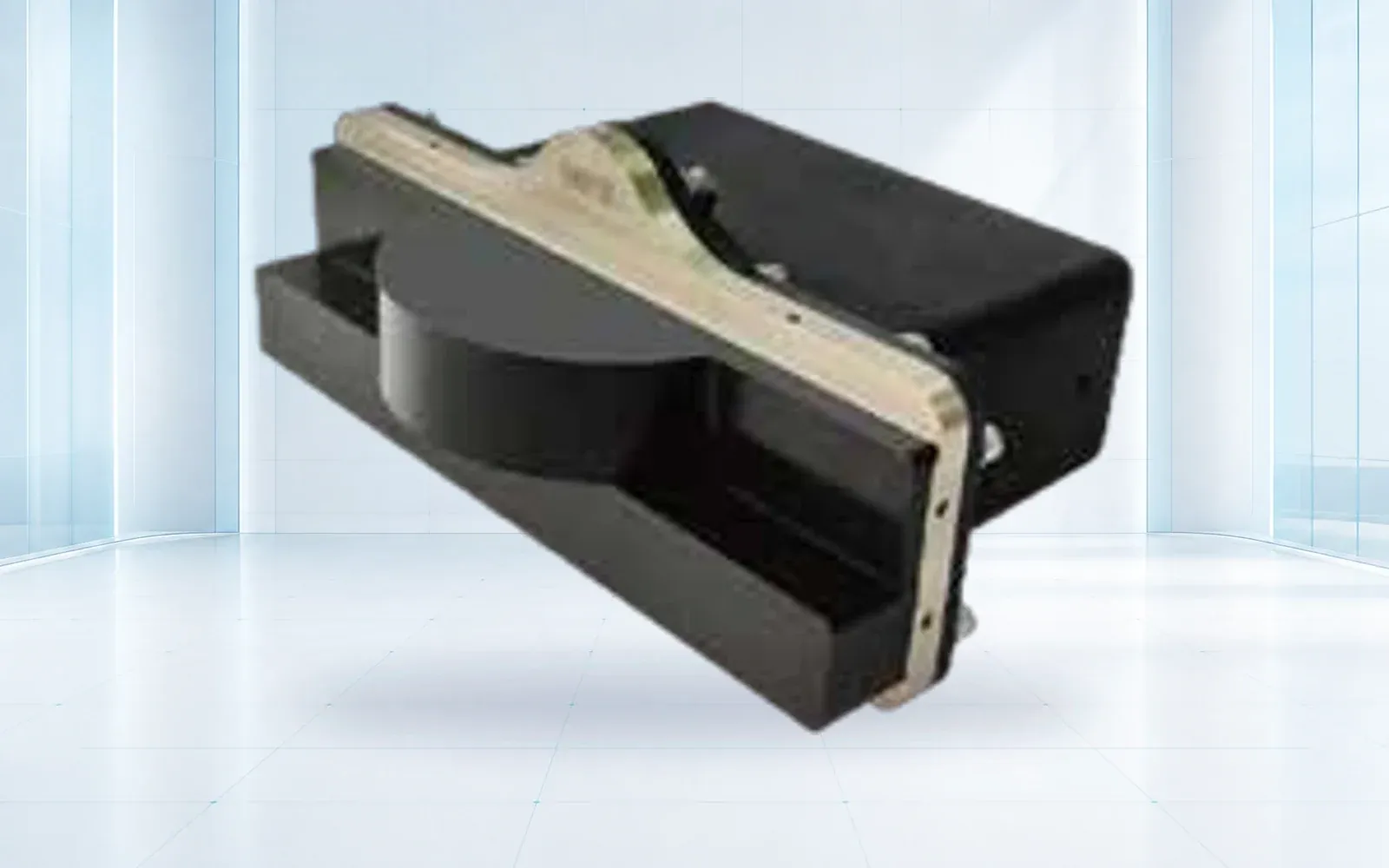
The SNR-C400 imaging sonar is a reference for low-visibility target acquisition, while the G70 work-class ROV represents a vehicle class for inspection and intervention payloads. Procurement must confirm the offered sonar, positioning, manipulator, tether, power and tooling as one installed system.
4. Control Stand-Off, Speed, Lighting, and Marine Growth
Set a pass speed and stand-off range that deliver the required detail while preserving vehicle control. A fast transit can create apparently continuous video with motion blur and gaps. Too little stand-off narrows the field of view and raises collision risk; too much stand-off reduces optical detail and light effectiveness.
Lighting should reveal surface texture without saturating suspended particles. Separate lights from the camera when practical to reduce backscatter, and test angles against wet reflective surfaces. Marine growth may hide coating or metal condition. If cleaning is in scope, define where, how and with what safeguards; a clean-looking image cannot be assumed where the surface was never exposed.
Current, tether drag and snag points shape the route. Establish vehicle and support-vessel abort limits, lost-navigation behavior, recovery options and a minimum reserve. The ROV operator should be able to stop collection when control or data quality falls below the plan rather than completing a low-value pass for schedule reasons.
5. Record Anomalies and Surrounding Seabed Consistently
An anomaly record should contain line and segment ID, route reference, coordinate and uncertainty, time, vehicle and sensor configuration, observation type, dimensions with method, original media, surrounding condition, confidence and required follow-up. Use controlled terms such as observed coating discontinuity, debris contact or free-span candidate; reserve corrosion depth and fitness conclusions for methods that support them.
Capture an overview, approach, stable detail and departure context. For free spans, record both shoulders and the surrounding seabed using an accepted geometry method. For crossings and supports, show how the pipe relates to the other structure. Do not crop away evidence that explains scale or location.
The BSEE Robotic Assistive Smart Touch project addresses autonomous navigation toward pipelines and robotic contact. Its 2026 research product is useful evidence of active development, but a research result should not be presented as proof that arbitrary subsea contact inspection is autonomous or production-ready.
6. Escalate to Qualified Integrity Assessment
Use a staged review. The ROV team confirms collection quality and route identity. A qualified reviewer classifies observations and requests missing views. The integrity team selects contact NDT, engineering analysis, repair, monitoring or no further action. Preserve every transition and the reason for it.
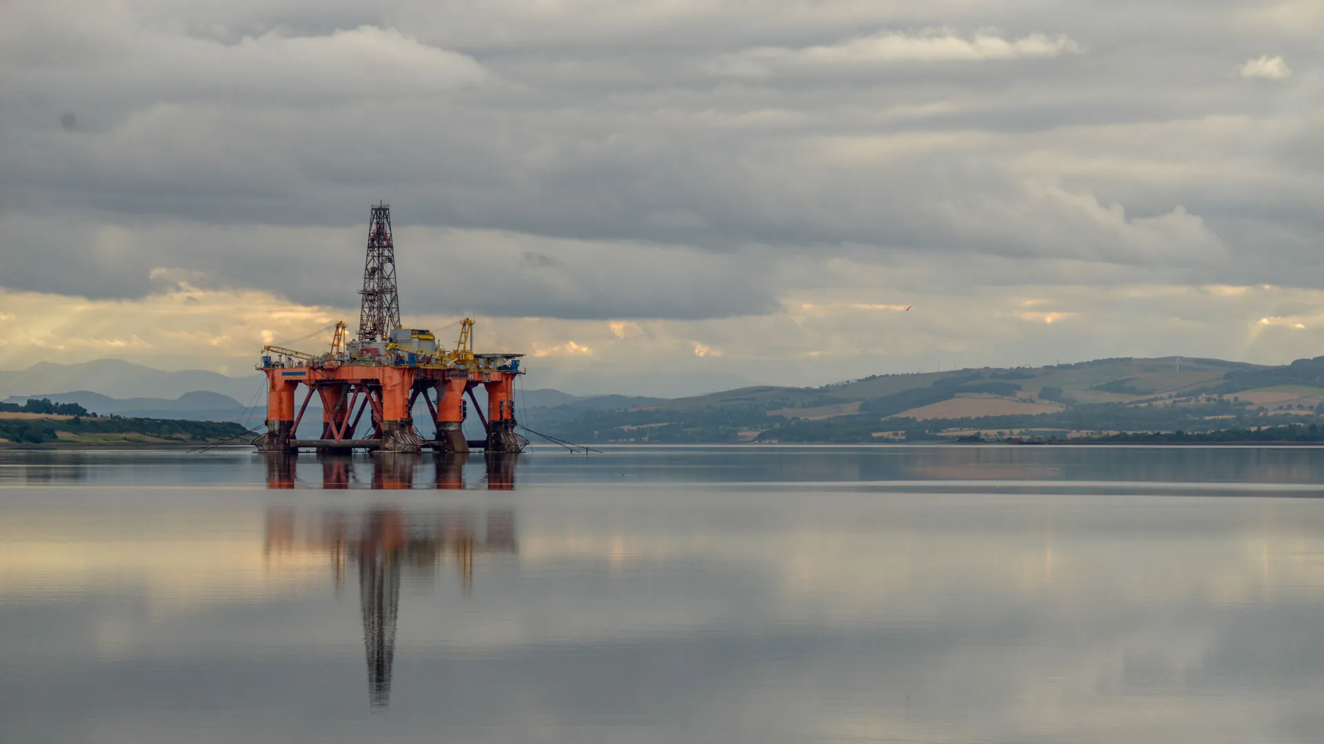
Regulatory scope depends on location, facility and pipeline type. The PHMSA guidance portal is a U.S. starting point, while offshore facilities may involve other authorities and owner standards. The inspection plan should identify applicable requirements rather than borrowing a patrol interval or record rule from a different pipeline context.
Use the oil and gas facility solution to connect subsea inspection findings with facility asset and response systems. The ROV side-scan and imaging-sonar guide helps separate search, imaging and identification tasks before payload selection.
7. Accept the System on a Representative Route
Build a trial with straight pipe, bends, supports, crossings, burial transitions, marine growth, low visibility and current. Include known targets and clean sections. Score route and surface coverage, position error at checkpoints, target detection, dimension repeatability, video and sonar rejection rates, false candidates per review hour, data synchronization and recovery after navigation degradation.
Follow selected observations into the integrity workflow. Confirm that another team can locate the same feature, understand the evidence and see the final disposition. State the valid operating envelope and retest triggers for changed sonar, navigation, tooling, software, vehicle or route conditions.
Review the underwater ROV portfolio and contact OMNI UXV with the route register, integrity questions, visibility and current envelope, positioning basis, required tooling and evidence schema for a representative trial.
8. FAQs
When does an ROV pipeline inspection need imaging sonar?
Imaging sonar is useful when turbidity, darkness, range or geometry prevents dependable visual acquisition. It can support target finding and structural context, but its resolution and interpretation limits must be tested for the anomaly types in scope.
How is an underwater pipeline observation positioned?
Position may combine surface-vessel navigation, acoustic positioning, vehicle sensors, tether or odometry data and pipeline chainage. The report should state the reference, method and uncertainty rather than treating the displayed ROV coordinate as exact.
Can an ROV camera measure pipeline wall thickness or corrosion depth?
Ordinary video cannot establish remaining wall thickness or hidden corrosion depth. Those decisions require an appropriate calibrated contact or non-destructive test method, suitable surface condition and qualified interpretation.
What should an ROV pipeline acceptance route contain?
Use representative pipe diameters, bends, crossings, burial transitions, marine growth, low visibility, current, free-span geometry, known targets and clean sections so coverage, positioning and false-candidate burden can be measured.