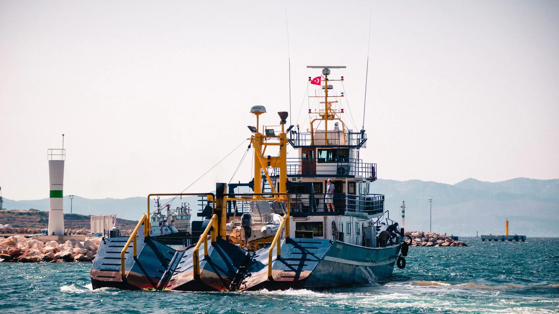
A multibeam echosounder does not produce an accepted depth surface by itself. The survey result depends on acoustic travel time, sound speed, position, motion, mounting geometry, synchronization, water level, line planning, processing and quality control operating as one measured system.
Table of Contents
- Define the Survey Order and Required Seafloor Decision
- Understand What a Multibeam Echosounder Actually Measures
- Build the Complete Position, Motion, Sound-Speed, and Time Chain
- Design Coverage, Frequency, Swath, and Line Spacing Together
- Calibrate Installation Biases and Verify the System at Sea
- Control Data Quality, Uncertainty, and Feature Detection
- Accept the Survey Deliverables, Not Only the Sonar Hardware
- FAQs
Define the Survey Order and Required Seafloor Decision
Start with the use of the data: navigation safety, dredging quantity, berth clearance, scour monitoring, engineering design, cable route, object search or habitat mapping. The decision determines the survey order, required feature size, coverage, horizontal and vertical uncertainty, density, deliverables and quality evidence.
Record the coordinate reference system, vertical reference, water-level method, area boundary, overlap, object-detection requirement and treatment of hazards. If a client asks for an “IHO survey,” identify the applicable order and any project requirements that are more stringent.
The International Hydrographic Organization publishes S-44 Edition 6.2.0 and maintains the current status through its standards and specifications page. Use the adopted document in the contract rather than a copied summary or an equipment brochure.
Understand What a Multibeam Echosounder Actually Measures
A multibeam echosounder transmits acoustic energy and receives returns across many beam directions. It measures travel time and angle-related information; depth points are computed after sound speed, transducer position, vessel motion and reference frames are applied. NOAA Ocean Exploration provides a clear public explanation of multibeam sonar.
The return selected as the seabed can be affected by slope, sediment, vegetation, bubbles, multipath and acoustic shadows. Outer beams cover more width but often have less favorable incidence and longer paths. More sounding points do not automatically mean more independent or more accurate information.
A system such as the SNR600C multibeam sounder should therefore be reviewed as one part of the measurement chain. Frequency, beam formation, depth range and interfaces must be taken from the offered configuration and tested in representative water.
Build the Complete Position, Motion, Sound-Speed, and Time Chain
Every depth is a combination of measurements and transformations. Document the source, resolution, rate, time base, lever arm, alignment and quality status of each input.
| Chain element | Contribution | Common failure | Verification evidence |
|---|---|---|---|
| Transducer and processing | Travel time, beam direction and bottom detection | Noise, bubbles, saturation or wrong detection | Raw acoustic data, settings and test lines |
| Surface sound speed | Beam steering at the transducer | Intake location or delayed update | Calibrated reading and comparison check |
| Sound-speed profile | Refraction through the water column | Spatial or temporal mismatch | Profile log, location, time and cast rationale |
| GNSS position | Horizontal sensor location | Poor correction, masking or antenna issue | Quality flags and independent check |
| IMU or MRU | Roll, pitch, heading and heave | Bias, latency or saturation | Calibration, quality log and comparison line |
| Lever arms and alignments | Transform between sensors | Survey or entry error | Signed installation survey and patch test |
| Time synchronization | Align all observations | Offset, drift or different time bases | Timing architecture and latency test |
| Water level or vertical reference | Reduce depths to project datum | Wrong datum or incomplete model | Datum statement and cross-check |
Do not hide failed or interpolated inputs in processing. The quality record should show when a sensor was invalid and which data were rejected or reprocessed.
Design Coverage, Frequency, Swath, and Line Spacing Together
Line spacing depends on depth, usable swath, seafloor relief, object-search requirement, vessel motion and expected data quality. A nominal angular swath may not be usable to its edge in rough water or on a steep slope. Plan overlap from the accepted portion of the swath.
Select frequency and pulse settings for depth, footprint, absorption and target needs rather than defaulting to the highest nominal resolution. Run cross lines and additional lines around structures, slopes and shadows. If the project requires feature detection, demonstrate the search method with appropriate reference features or independent confirmation.
Side-scan sonar can complement the bathymetric surface with intensity imagery. The SNR900U side-scan sonar and the sonar method selection guide help define that boundary without treating side scan as a depth substitute.
Calibrate Installation Biases and Verify the System at Sea
Survey the antenna, motion sensor and transducer reference points in one vessel frame. Record sign conventions and uncertainty. A patch test then estimates residual roll, pitch, heading and timing effects using line patterns and seabed geometry suitable for each parameter.
Calibration is not permanent. Repeat or verify it after a transducer, bracket, sensor, computer, cable, timing source or vessel geometry changes; after an impact; or when cross-line residuals indicate a problem. Record software and firmware versions alongside the calibration result.
Conduct a performance or reference-area check before production. The goal is to confirm that the installed system, crew and processing chain reproduce a known or internally consistent result under current conditions.
Control Data Quality, Uncertainty, and Feature Detection
Build an uncertainty budget from the actual system and environment. Report total horizontal and vertical uncertainty as required by the project rather than quoting a sonar precision value. Check cross-line differences, reference surfaces, density, gaps, outer-beam behavior, sound-speed artifacts and rejected data.
Quality control should be visible in the deliverable: coverage plots, uncertainty surfaces, data-density plots, sound-speed records, navigation and motion quality, calibration, tide or water-level evidence, object-detection results and a processing log. A smooth surface can still be wrong if the inputs share a bias.
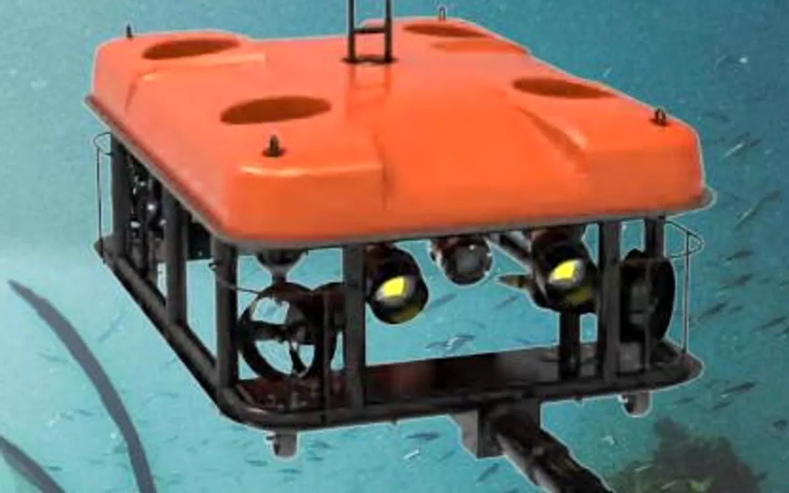
Where an anomaly matters to engineering, use a targeted line, diver or G70 work-class ROV to confirm it. Preserve the relationship between the wide-area bathymetry and close observation in the port asset evidence lifecycle.
Accept the Survey Deliverables, Not Only the Sonar Hardware
Hardware acceptance checks function, interfaces and configuration. Survey acceptance evaluates whether the complete project satisfies order, coverage, uncertainty, feature, datum, metadata and delivery requirements. Keep these gates separate so a functioning sonar is not mistaken for an accepted charting or engineering product.
NOAA publishes its current hydrographic survey specifications and deliverables, which illustrates how a client specification controls field records, quality and formats in addition to general standards. Other clients and jurisdictions may require different deliverables.
Accept raw sensor data, navigation and motion data, sound-speed data, configuration, calibrations, project database, processed soundings, surfaces, features, quality layers, reports and a reproducible export. Document software dependencies and any area that did not meet the order.
Use the port and water security solution to connect survey outputs with port operations, and the resource library to prepare the order and delivery checklist. For a configuration and acceptance review, contact OMNI UXV with the survey purpose, depth range, order, platform and required deliverables.
FAQs
What is the difference between multibeam and side-scan sonar?
A multibeam echosounder is designed to measure many depth points across a swath with position and uncertainty, while side-scan sonar emphasizes acoustic intensity imagery of the seabed. The methods can complement each other but do not produce interchangeable deliverables.
Can a multibeam echosounder by itself be IHO S-44 compliant?
No. S-44 applies requirements to a hydrographic survey and its results. Compliance depends on the complete measurement system, procedures, feature search, uncertainty, quality control and deliverables, not only the sonar model.
Why does a multibeam survey need sound-speed measurements?
The system converts acoustic travel time into range using sound speed, and refraction through a changing water column alters the beam path. Surface and profile measurements are needed at a frequency appropriate to the water conditions and survey specification.
What is a multibeam patch test?
A patch test estimates residual alignment and timing biases among the sonar, position and motion sensors using designed survey lines over suitable seabed. It must be documented and repeated after relevant installation or system changes.