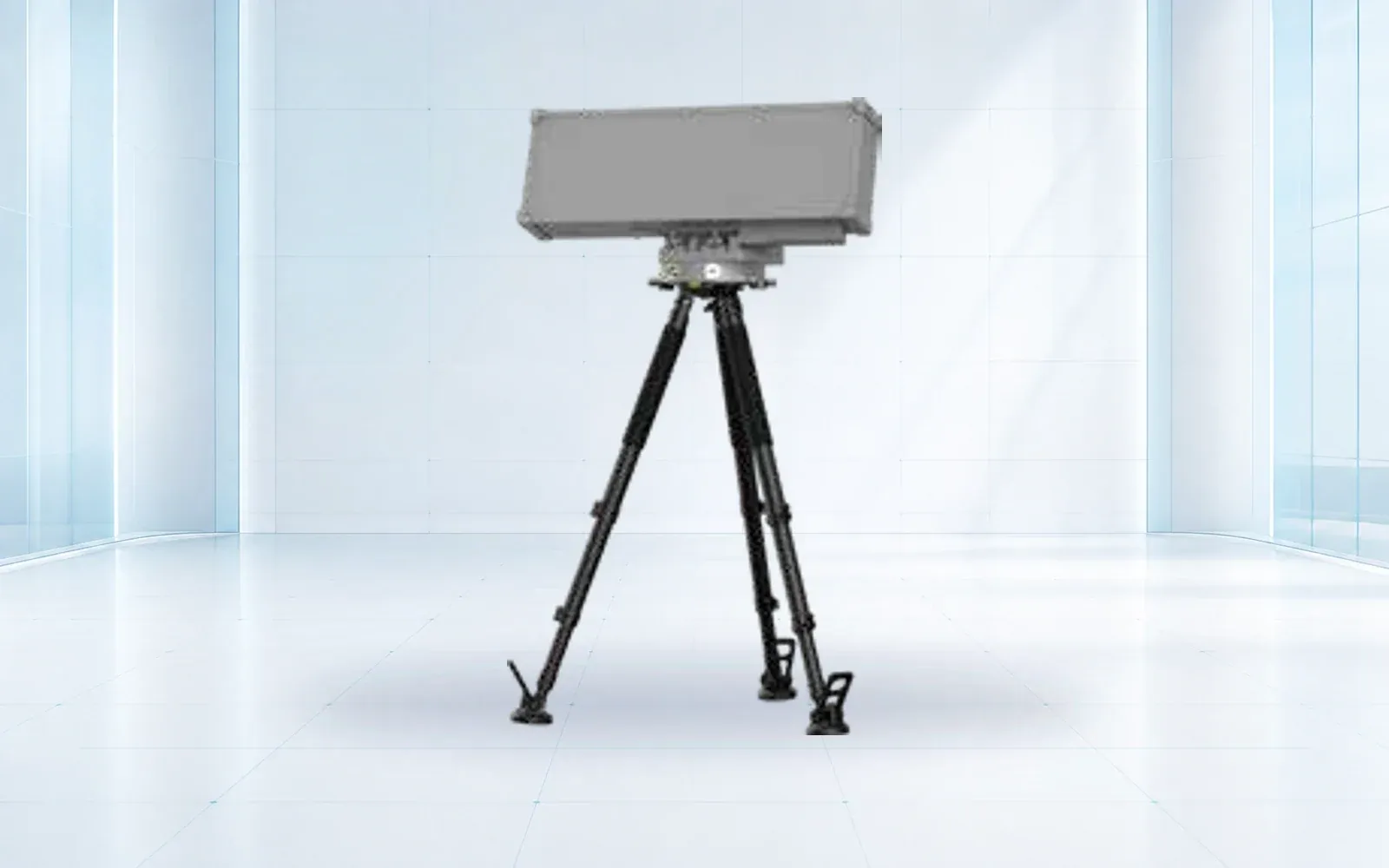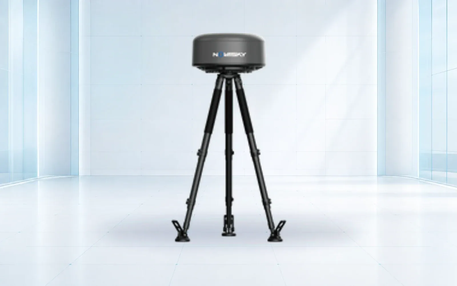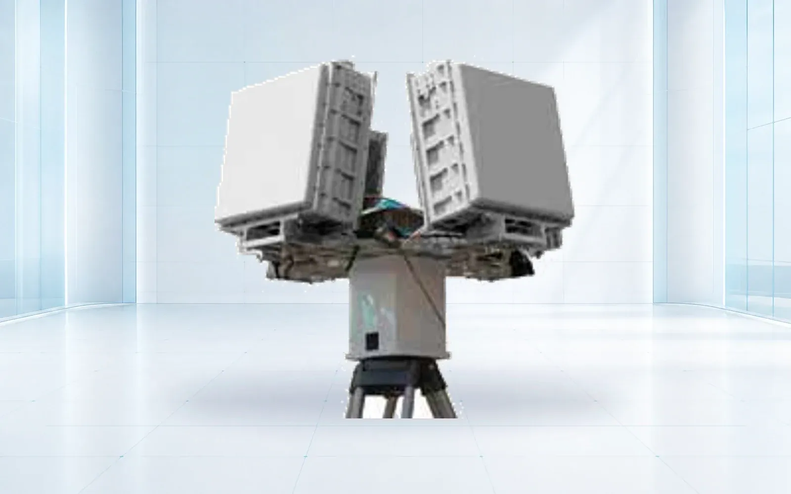
Counter-drone radar placement is a three-dimensional coverage problem shaped by the protected volume, terrain, buildings, vegetation, approach altitude, target aspect, ground clutter, multipath, electromagnetic coordination, structure, maintenance access, power, network, and the geometry of the verification sensor.
Table of Contents
Draw the Protected Volume in Three Dimensions
Begin with assets, consequence zones, authorized air activity, approach corridors, required warning time, and the operator’s response workflow. Draw horizontal boundaries together with altitude bands and terrain. A circle around a radar coordinate hides the low-altitude paths that matter most.
For each sector, state the target classes to be evaluated, minimum relevant altitude, route direction, required output, verification method, and acceptable unobserved area. If the site cannot define these fields, a range requirement is premature.
CISA’s Be Air Aware materials place technology inside a broader risk, incident-plan, and authority process. Radar siting should follow that process rather than becoming the site’s entire UAS security plan.
Profile Terrain, Structures, Vegetation, and Change
Use current survey or reliable site geometry to create radial profiles through critical approaches. Include buildings, tanks, cranes, stacks, towers, walls, berms, cut slopes, trees, temporary works, and planned construction. Record the elevation datum and coordinate system shared with the command platform and cameras.
| Sector register field | Design question | Verification |
|---|---|---|
| Minimum visible altitude | Where does terrain or a structure mask the route? | Surveyed profile plus authorized flight |
| Clutter source | Which moving or reflective objects occupy the beam? | Timed observation and radar record |
| Sector transition | Can one track cross between sensors without a gap or duplicate? | Cross-boundary truth route |
| Verification geometry | Can EO/IR see and slew to the radar track? | Coordinate and live-cue test |
| Change risk | What construction, foliage or equipment can alter coverage? | Owner change register and retest trigger |
Model seasonal vegetation and movable equipment as variables. A clear commissioning view can become a shadowed corridor after foliage growth, container stacking, or crane relocation.
Observe Clutter and Multipath Before Final Mounting
Roads, rail, water, rotating machinery, fans, flags, birds, surface vehicles, nearby aircraft, and reflective structures can produce recurring observations. Record them by time, weather, sector, and operating state. Use a temporary or survey mount where practical to compare candidate positions before civil work is frozen.
Do not solve every clutter source with an exclusion zone. A mask can also remove a required low route. Trace each setting to the protected-volume requirement and plan a target regression test.
FAA airport material notes that radar and even nominally passive systems can raise site-specific electromagnetic, licensing, structure, and airspace coordination issues. Airport projects should begin coordination with the responsible FAA office before deployment; other sites must identify their own spectrum, planning, structural, and legal authorities.
Engineer the Mount, Power, Network, and Maintenance Path
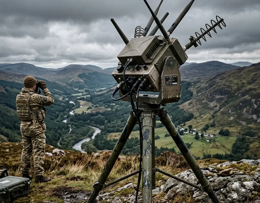
Specify coordinate, height, orientation, leveling, structural stiffness, vibration, wind and environmental loads, lightning and surge protection, grounding, drainage, enclosure, cable routes, network, time source, backup power, and safe access. A tall position that cannot be safely maintained or surveyed is not operationally complete.
Protect the administrative path and log configuration changes. Define how the platform reports power loss, network loss, clock error, stale data, antenna movement, blocked view, or degraded processing. Plan a recoverable configuration and a field method for confirming the sensor has returned to its accepted orientation.
Check Camera Cueing as a Geometry Problem
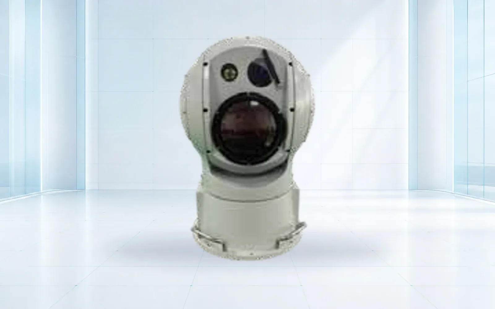
Map radar and EO/IR coordinates in the same reference system and confirm terrain elevation, boresight, slew limits, field of view, focus, latency, and update rate. A camera placed beside a radar can still be blocked by a parapet, structure, or the same low-altitude obstacle.
Use the radar-to-camera handoff guide to test track-to-pixel performance. Keep visual verification limits separate from radar coverage; night, weather, background, and target size affect the camera differently.
Verify Every Critical Sector in the Field
The site model creates test routes, not proof. Fly authorized representative targets through critical profiles, sector edges, low corridors, clutter boundaries, and camera handoff points. Synchronize truth and score detection, track continuity, alert timing, cue result, and blind areas.
Then run the counter-drone radar acceptance plan across the full configured site. Retain coordinates, drawings, photos, obstruction record, settings, truth, results, exceptions, and retest triggers.
Compare candidate radar configurations in the counter-UAS category, including NI-QR5000 and NI-R5000. The border and homeland-security solution and resource center connect sector design to response, evidence, and lifecycle control.
FAQs
Should a counter-drone radar always be installed at the highest point?
No. Height can improve some lines of sight but can also change near-field coverage, ground clutter, structural loading, maintenance access, cable runs, spectrum coordination, and camera handoff geometry.
How do buildings affect counter-drone radar coverage?
Buildings can block low-altitude paths, create shadowed sectors and contribute reflections or multipath. The site model should be verified with representative routes instead of relying only on a plan-view radius.
What should a counter-UAS radar site survey deliver?
Deliver a protected-volume model, sector register, terrain and structure profile, obstruction and clutter map, candidate coordinates and heights, infrastructure plan, coordination actions, field-test routes, and recorded blind areas.