A drone solar panel inspection is useful when a technician can locate the reported module, understand the evidence and decide what to test next. A colorful thermal mosaic alone cannot do that. Specify radiometric data, acquisition conditions, asset identifiers and ground verification before choosing the aircraft or quoting the flight.
Table of Contents
- 1. A Thermal Map Must Lead to a Maintenance Decision
- 2. Specify the Thermal Evidence Before the Aircraft
- 2.1. Keep thermal and visible images together
- 3. Treat Weather and Plant State as Measurement Inputs
- 4. Turn Hot Areas into Testable Hypotheses
- 5. Build a Module-Level Evidence Chain
- 6. Price the Inspection by Usable Findings
- 7. FAQs
1. A Thermal Map Must Lead to a Maintenance Decision
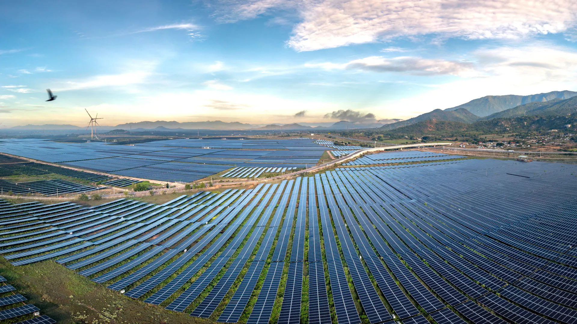
Solar assets are accumulating faster than many owners can inspect them manually. The IEA PVPS Snapshot of Global PV Markets 2026 estimates that worldwide installed photovoltaic capacity approached 3 TW in 2025. That is context for a growing maintenance workload, not a measurement of the drone inspection market or a forecast of an individual site’s savings.
Start with the maintenance question. Is the inspection a baseline after commissioning, a periodic condition assessment, a response to underperformance or a check after a repair? Each requires a different comparison and may need different plant records.
A useful finding ends at a recognizable asset. “Hot area near the southern edge” is weak evidence if technicians must search hundreds of modules to locate it. Agree on site, block, inverter, string, row and module conventions with the operator. Where the asset register is incomplete, include reconciliation in the scope rather than treating it as free work after the flight.
The objective is a defensible list of observations and next actions. Do not equate the number of colored boxes generated by software with confirmed defects.
2. Specify the Thermal Evidence Before the Aircraft
Radiometric data preserve temperature-related measurement information; a palette-colored screenshot may preserve only a visual rendering. State what original files the owner will receive, what calibration and camera settings accompany them and whether the analysis can be revisited without the vendor’s account.
Resolution must be evaluated at the module and feature level. A camera’s pixel count by itself does not tell the client how many usable pixels represent a suspected cell pattern at the planned distance and viewing angle. Test the proposed optics, flight geometry and processing on representative modules.
The public scope of IEC TS 62446-3:2017 covers outdoor infrared inspection of operating PV modules and plants, including equipment, conditions, procedure, reporting and personnel. As checked on August 25, 2026, the IEC catalog still marked that edition valid and the next edition under development. Obtain the applicable full specification before making a contractual conformity claim; this article does not substitute for its requirements.
2.1. Keep thermal and visible images together
A thermal finding is easier to interpret when the associated visible image shows module boundaries, shadows, contamination and nearby objects. Confirm that the two records refer to the same asset and acquisition period. A misregistered overlay can send a technician to the wrong module even when the thermal observation itself is sound.
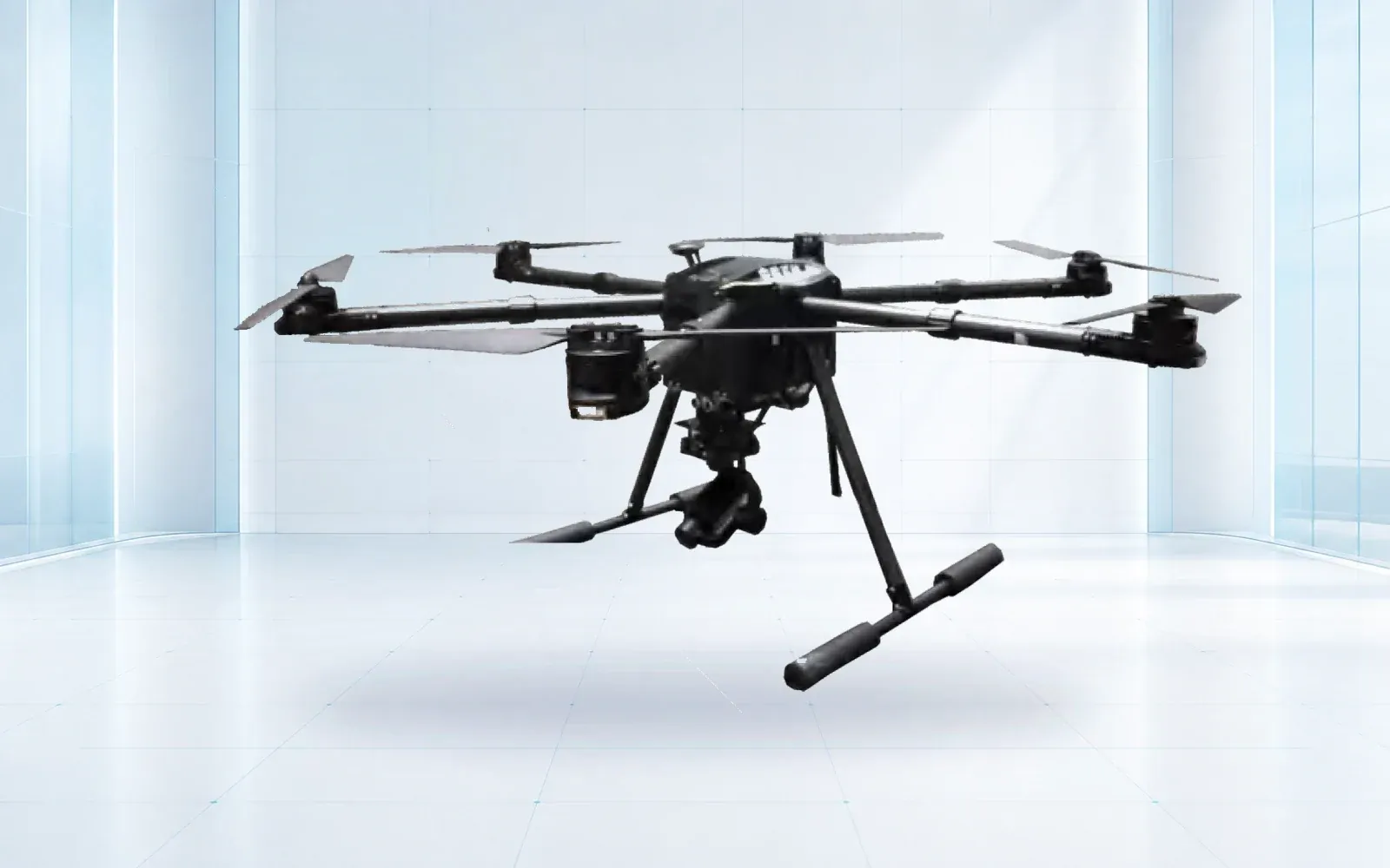
The F4 multirotor is a possible carrier for visible and thermal payload configurations. That does not establish that every supplied camera is radiometric or that the combination meets an inspection standard. Ask for the exact sensor, calibration record, file formats and demonstrated sample output.
3. Treat Weather and Plant State as Measurement Inputs
Cloud transitions, wind, surface moisture and changes in electrical loading can alter the thermal scene. A flight plan should define acceptable acquisition conditions under the chosen inspection procedure and explain what happens when they change.
Record conditions with enough timing information to connect them to images. A single weather observation taken at the start of a long survey may not explain a later section. Preserve the plant operating state as well: an isolated string and a normally loaded string are not interchangeable measurement conditions.
Reflection is another source of confusion. Module glass can reflect the sky, surrounding objects or the aircraft. Inspect suspicious patterns from an appropriate alternative view when the approved procedure allows it, and compare visible imagery before assigning a fault category.
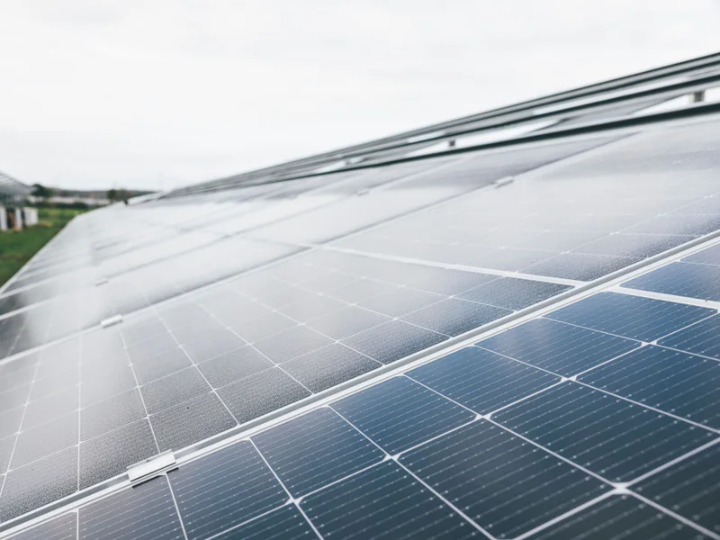
The IEA PVPS guidance on climate-specific operation and maintenance describes why maintenance programs need to account for environmental stresses. For a drone inspection, the engineering implication is to preserve local conditions and seasonal context rather than compare unlike images as if they were repeat measurements.
4. Turn Hot Areas into Testable Hypotheses
The following matrix is a way to organize follow-up, not a remote diagnostic rule. Electrical testing and interventions belong to appropriately qualified personnel working under the site’s safety procedures.
| Observed pattern | Questions to investigate | Additional evidence | Record in the finding |
|---|---|---|---|
| Localized warmer area | Is it persistent, shaded, contaminated or associated with visible damage? | Paired RGB image, repeat observation and suitable electrical checks | Exact module and feature, conditions and confidence |
| A warmer group or string pattern | Does the electrical layout explain the pattern? | String/inverter records and field verification | Asset hierarchy and suspected grouping |
| Broad temperature difference | Did loading, wind, cloud or orientation change? | Operating-state and acquisition logs | Whether comparison conditions are equivalent |
| Bright region that changes with view | Could it be a reflection? | Alternative view and visible context | Why it was retained or rejected |
| Missing or unusable coverage | Was the area inaccessible or acquired outside the procedure? | Flight and quality-control records | Reinspection requirement, not a “normal” classification |
Keep observed facts separate from interpretations. “Temperature pattern observed under these conditions” is different from “failed bypass diode confirmed.” The report should show which stage the finding has reached and who confirmed it.
Avoid assigning a universal energy-loss value to every anomaly class. Converting an image into lost revenue needs electrical context, duration, energy yield and an agreed calculation method. If those inputs are absent, report that the financial effect has not been established.
5. Build a Module-Level Evidence Chain
Create a stable finding identifier that follows the issue from inspection to verification, work order, repair and reinspection. Keep the original observation even if the later diagnosis changes. This makes it possible to distinguish a false positive from a genuine issue that was repaired.
The handover should include original imagery, the asset map, analysis output, acquisition records, a list of excluded areas and a machine-readable finding register. Confirm how coordinates and asset IDs survive export into the owner’s maintenance system.
Software may help prioritize review, but uncertain results still need a human decision. Define an unclassified state rather than forcing every image into normal or faulty. Measure agreement between reviewers on a representative sample and investigate systematic disagreement.
A repeat inspection should locate the same asset and record whether conditions are comparable. A visually cooler module after maintenance is not, by itself, proof that the electrical problem has been resolved.
6. Price the Inspection by Usable Findings
Compare proposals on the same scope: verified area, operating windows, raw-data delivery, asset reconciliation, analysis, ground follow-up, reporting and reinspection. A per-megawatt price without those inclusions can hide much of the work.
Acceptance should test whether maintenance staff can retrieve a finding, locate the asset and understand the next action without asking the analyst to reconstruct the flight. Include unreadable images, uncertain IDs and inaccessible areas in the review. Those exceptions matter as much as the best sample images.
The industrial UAV range and critical-infrastructure solution provide the equipment and system context. Use the product catalog to request a named payload configuration, and the industrial datasheet guide to separate aircraft claims from inspection deliverables.
For a practical scope review, share the site layout, module register, operating constraints and required maintenance output with OMNI UXV.
7. FAQs
Can a thermal drone identify every faulty solar module?
No. Aerial thermal imaging can reveal patterns that warrant investigation, but visibility depends on operating conditions, image quality and the fault itself. Some findings require electrical tests, close visual checks or another inspection method.
Does a hotspot prove that a solar panel needs replacing?
No. A hot area may be associated with shading, contamination, electrical behavior, damage or a reflection. The finding needs contextual evidence and appropriate ground verification before a repair or replacement decision.
What should a solar inspection report contain?
Include asset and module identifiers, paired visual and thermal evidence, acquisition time and conditions, anomaly classification, confidence, coverage limitations and the next verification action. Link confirmed findings to maintenance records.
Is IEC TS 62446-3 a new 2026 standard?
No. At the August 25, 2026 review, the IEC catalog listed the 2017 edition as valid and a second edition under development. A project should identify the applicable published edition and obtain its full requirements before claiming conformity.