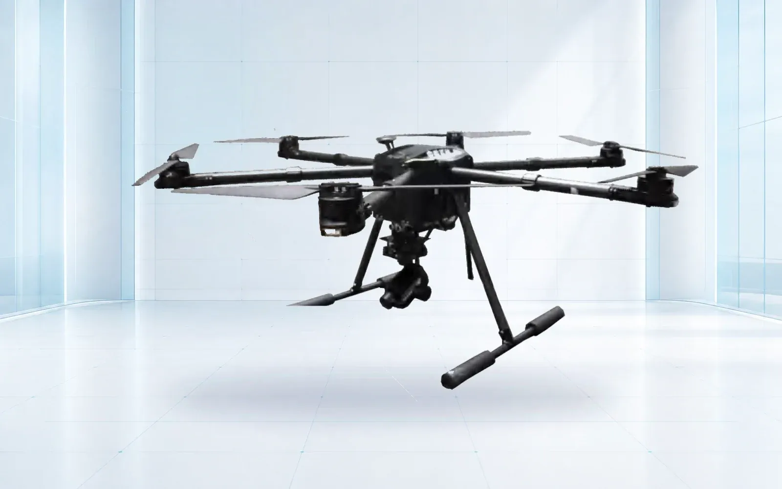
Drone payload integration is an aircraft-level engineering change, not a bracket purchase. A credible integration freezes mass and center of gravity, mounting, power quality, thermal behavior, command and data interfaces, time, failure modes, configuration records, and representative flight acceptance.
Table of Contents
Treat the Payload as Part of the Aircraft System
A camera, radar, searchlight, loudspeaker, sampler, release device, or communications relay changes more than takeoff mass. It can move the center of gravity, add drag, obstruct antennas, inject electrical noise, consume reserve energy, alter emergency behavior, and introduce new software or data-security boundaries.
Start with a configuration identifier that names the exact aircraft, payload, mount, cabling, power module, firmware, ground software, data link, and operating mode. The integration is accepted against that baseline. Substituting a battery, mount, antenna, cable, or payload firmware may require impact review and partial retest.
FAA Advisory Circular 107-2 discusses loading, weight, balance, and center-of-gravity effects. Even when another jurisdiction or operating framework applies, the engineering lesson is durable: a maximum mass value does not prove safe handling in every environment or loading arrangement.
Build One Interface Control Matrix
Keep requirements, supplier responses, inspection evidence, and test results in one controlled matrix. Avoid separate mechanical, electrical, and software lists that can contradict one another.
| Interface | Freeze before purchase | Verify during integration | Evidence at delivery |
|---|---|---|---|
| Mass and balance | Installed mass, CG coordinates, allowable envelope | Weigh complete configuration and check loading cases | Signed configuration and measurement record |
| Mechanical | Envelope, fasteners, load paths, release prevention | Fit, clearance, retention, vibration and inspection access | Drawings, torque/retention record, photos |
| Power | Voltage, steady and transient draw, inrush, protection | Start, peak mode, brownout, isolation and shutdown | Logged voltage/current and fault results |
| Thermal/environment | Dissipation, airflow, temperature, water/dust boundaries | Ground soak and representative operating exposure | Temperature and condition record |
| Command/data | Protocol, message, update rate, storage, export | Command latency, dropped link, file integrity | Interface version and sample dataset |
| Safety behavior | Arm state, inhibit, loss-of-link and emergency action | Inject faults and confirm predictable state | Failure-case checklist and operator cues |
Define units, coordinate axes, connector pinouts, message versions, timestamps, ownership, tolerances, and test method. “Ethernet,” “12 volts,” or “compatible mount” is not an interface specification.
Resolve Mass, Balance, Mounting, and Aerodynamics Together
Locate the payload center of mass, not only its total mass. Include brackets, dampers, cable loops, protective housing, antennas, storage, and accessories. Evaluate every permitted loading state, including moving gimbals, consumables, retained samples, and released cargo where applicable.
Document the structural load path and retention features. Check landing clearance, sensor field of view, rotor or propeller clearance, airflow, access to fasteners, emergency jettison policy if any, and whether a failure can create a falling-object or entanglement hazard.
External geometry can change drag and control margin. Verify takeoff, transition where applicable, climb, cruise, turns, descent, landing, and relevant wind directions with the installed configuration. Do not infer behavior from a payload of equal mass but different shape or location.
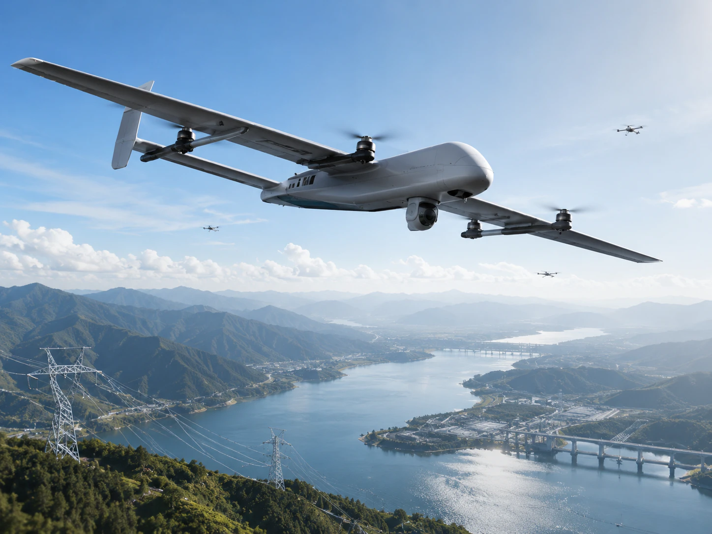
Test Power, Heat, Electromagnetic Interaction, and Time
Measure steady draw, inrush, peak operating modes, heater or illumination loads, and shutdown behavior. Test with representative battery state and other aircraft loads active. A bench supply that never sags does not reproduce a flight power bus near a demanding maneuver or reserve threshold.
Record component temperatures during ground soak and flight. Ground operation may reduce airflow, while solar loading or an enclosure can create a different hot spot. Define a visible over-temperature state and the safe response.
Check GNSS, command link, telemetry, compass, video, and other payloads while the new device cycles through modes. Synchronize aircraft time, payload time, and ground records. If a finding must be mapped or correlated with another sensor, an unknown clock offset can invalidate otherwise clear data.
Define Data Ownership and Failure Behavior
Specify raw and processed files, metadata, coordinate frame, units, compression, encryption, retention, export, and recovery after interrupted recording. Decide whether the aircraft, payload, controller, or cloud service owns mission identifiers and time. Protect administration and update paths using the same access-control and change-management discipline described in the NIST Cybersecurity Framework 2.0.
Inject failures: payload boot failure, frozen gimbal, full storage, corrupted file, lost command, lost video, high temperature, excess current, network loss, and aircraft failsafe. The operator should receive an unambiguous state and retain aircraft control. A silent payload failure must not be recorded as a successful mission.
Progress From Bench Evidence to Representative Flight
Use staged gates: requirements and drawings; fit and inspection; bench power/data; restrained or manufacturer-approved ground operation; limited flight; representative mission; failure and recovery; repeat mission; evidence review. Stop at each gate until the observed configuration matches the controlled record.
Score aircraft controllability, mission reserve, vibration or image quality, command and data latency, link coexistence, thermal margin, file completeness, georeferencing, operator workload, and failure visibility. The drone endurance planning guide turns the measured power and mission profile into a usable flight budget, while the heavy-lift selection guide helps determine whether the platform class is appropriate before integration begins.
Use the industrial UAV category to review candidate airframes, the disaster-response solution to place payloads in a mission architecture, and the resource center to organize interface and acceptance documentation.
FAQs
What belongs in a drone payload interface control document?
Record physical envelope, mass and center of gravity, fasteners, loads, power and protection, grounding, thermal limits, command, telemetry, data formats, time synchronization, software versions, environmental sealing, and failure behavior.
Can a payload be compatible if it is below the drone's maximum payload mass?
Not necessarily. Compatibility also depends on center of gravity, mount loads, vibration, aerodynamic effects, power transients, cooling, electromagnetic interaction, data links, control logic, and the mission reserve.
How should an integrated drone payload be accepted?
Progress from document review and bench tests to fit, power, data, restrained operation, limited flight, representative missions, failure cases, and delivery of a configuration-linked evidence package.